Forged Universal Shaft Coupling

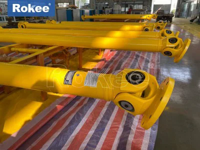
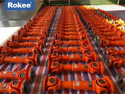
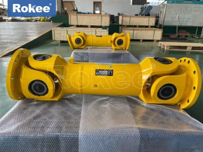
The forged universal shaft coupling stands as a robust mechanical transmission component engineered to transfer torque and rotational motion between shafts that cannot maintain perfect coaxial alignment, distinguishing itself from cast alternatives through the inherent material advantages brought by the forging process. Many mechanical systems encounter unavoidable misalignment during routine operation, whether from assembly tolerances, thermal expansion, structural deflection under heavy loads, or dynamic positional shifts between driving and driven equipment. Rigid couplings fail to accommodate these deviations, imposing intense bending stress on connected shafts, bearings and machine housings, while ordinary flexible couplings can only manage very limited angular offset. This forged variant solves the challenge by integrating articulated universal joints built from forged yokes and cross spiders, allowing sustained power transfer even when a measurable angular deflection exists between two shafts. The forging process rearranges the internal grain structure of the metal blank, aligning grain flow to follow the contour of each critical part such as yoke arms and cross journals, rather than letting grain boundaries form randomly as seen in cast components. This refined grain layout directly improves resistance to fatigue cracking, impact loading and torsional shear, which is essential for equipment operating under fluctuating loads. Every functional element, from the fork-shaped yokes to the central cross spider, is shaped under controlled compressive force, eliminating internal voids, porosity and shrinkage cavities that commonly weaken cast metal parts. As a result, forged universal shaft couplings can reliably handle heavy torque and shock loads that would quickly damage cast counterparts, making them a preferred choice for demanding power transmission layouts where downtime and component failure carry significant operational consequences.
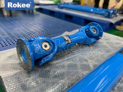
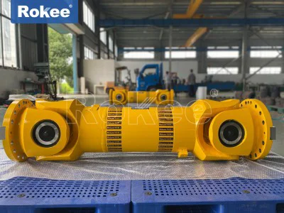
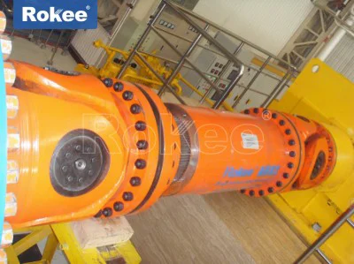
The basic mechanical structure of a forged universal coupling revolves around paired forged yokes, a precision-machined cross spider, sealed bearing assemblies and optional telescopic spline sections for axial length compensation. Each universal joint unit uses two yokes positioned perpendicularly relative to the four journals of the cross spider, with each journal seated inside a bearing assembly fitted within the bore of the yoke. As the driving shaft spins, the attached yoke rotates and drives the cross spider, which then transfers rotational force to the second yoke connected to the driven shaft. The cross spider can pivot freely within the bearings, creating a spatial hinge that accommodates angular misalignment while continuing to transmit torque. Single universal joint units produce minor speed fluctuations at larger deflection angles, so most industrial forged universal shaft couplings adopt a double-joint layout. In this configuration, the two yokes on the intermediate shaft are aligned properly to counteract speed variation, delivering near-constant rotational velocity to the output shaft. The telescopic spline segment, when included, slides inward and outward to compensate for axial distance changes between connected machines. This feature proves valuable when equipment expands thermally during operation or when relative movement occurs between machine frames. All load-bearing structural parts of this assembly, especially yokes and cross spiders, are forged, ensuring that the areas subjected to repeated torsional and impact stress maintain consistent structural integrity. The bearings are enclosed within sealed housings to retain lubricant and block dust, debris and moisture, reducing abrasive wear and extending the working lifespan of moving articulation surfaces.
The forging manufacturing process defines the core performance characteristics of the universal shaft coupling, starting from carefully selected metal blanks and progressing through sequential forming, heat treatment and precision machining steps. Raw metal stock is first heated to a suitable forming temperature, then compressed by powerful forging equipment to reshape the material into near-net-shape blanks for yokes and cross spiders. The compressive deformation closes internal material defects and stretches the metal grain lines to conform to the shape of each component. Unlike casting, which pours molten metal into a mold cavity, forging keeps the material in a solid state throughout forming, preserving a dense, continuous metallic structure. After forging, the rough forgings undergo heat treatment to adjust hardness, toughness and internal stress levels. This thermal processing relieves residual stress built up during mechanical deformation, preventing warping during later machining and service. Once heat treatment completes, computer-controlled machining cuts the bearing seats, flange mounting surfaces, spline profiles and bolt holes to tight dimensional tolerances. Fine grinding operations refine the journal surfaces of the cross spider to achieve smooth, uniform finishes that minimize friction and wear inside bearing assemblies. After machining, each component is inspected for surface flaws and dimensional accuracy before assembly. Finished couplings also receive surface finishing treatments that defend against oxidation and corrosion in humid or dusty working environments. Every stage of production is oriented toward ensuring that the forged parts can endure repeated cyclic torque loading without developing sudden fractures or progressive fatigue damage.
Material selection for forged universal shaft coupling components focuses on alloy grades that balance high tensile strength, impact toughness and hardening response, matching material properties to expected load profiles and environmental operating conditions. The yokes and cross spiders, which bear the majority of torsional and impact stress, are typically made from alloy steel formulated to harden evenly while retaining sufficient ductility to resist brittle fracture under sudden overload. The base metal responds well to thermal treatment, allowing surface hardening of critical contact journals while keeping the core material tough to absorb shock loads. Shaft tube sections may use seamless steel tubes, which pair with forged end yokes to form the complete coupling body. Material choice also considers environmental exposure, as some operating settings introduce moisture, chemical vapors or abrasive particles that accelerate surface degradation. While the base alloy provides mechanical strength, protective surface treatments add an extra barrier against rust and abrasion. Engineers select material specifications based on peak torque requirements, operating cycle frequency, deflection angles and ambient operating conditions. Under continuous heavy cyclic loading, the forged alloy maintains stable mechanical performance, resisting the initiation and propagation of fatigue cracks that often start at internal defects in cast components. Even during transient overload events, properly forged and heat-treated parts tend to deform gradually rather than shatter catastrophically, offering an important safety margin for industrial transmission systems. This combination of strength and toughness is the primary reason forged construction remains favored over cast alternatives in high-load transmission applications.
Working performance of forged universal shaft couplings shows clear advantages in handling combined misalignment types, heavy torque transmission and dynamic load fluctuations, though operating limits must be respected to avoid premature wear. The coupling simultaneously accommodates angular misalignment, limited axial movement and minor radial offset, removing the need for ultra-precise shaft alignment during equipment installation. This simplifies assembly work and reduces installation time for large machinery. The forged construction delivers high torsional stiffness, so rotational power transfers with minimal torsional deflection when torque loads are applied. Even with repeated shock loads, the forged structure maintains dimensional stability and avoids permanent deformation at rated working capacity. As the operating deflection angle increases, sliding friction inside the universal joint bearings rises, which generates more heat and accelerates wear. For this reason, operation at the upper limit of angular deflection requires careful monitoring and more frequent maintenance. Speed also affects performance; higher rotational speeds amplify centrifugal forces and heat buildup within joint assemblies, so design reviews must match coupling size and joint geometry to operating speed ranges. Properly configured forged universal shaft couplings maintain stable transmission efficiency over long operating cycles, and power loss across the coupling assembly remains relatively low under normal working conditions. When load spikes occur, the robust forged structure absorbs transient overloads better than many flexible couplings, protecting connected drive and load equipment from sudden impact damage.
Lubrication and maintenance practices directly influence the service life and reliability of forged universal shaft couplings, focusing on preserving bearing surfaces and reducing friction at articulation points. Lubricant fills the space between cross spider journals and bearing inner surfaces, creating a separating film that prevents metal-to-metal contact during rotation and pivoting movement. Without adequate lubrication, localized friction quickly generates excessive heat, scuffing the precision ground journal surfaces and leading to rapid bearing failure. Sealed bearing caps help retain grease inside the joint and block external contaminants, but seals can degrade over time from heat, vibration and environmental abrasives. Regular maintenance includes scheduled lubricant replenishment, visual inspection of seal integrity and checking for abnormal vibration or noise during operation. Vibration often signals worn bearings, loose fasteners or excessive misalignment that exceeds the coupling’s designed capacity. Operators should also check mounting bolts and flange connections to ensure clamping force remains consistent, as loose connections introduce shock loads and misalignment. During inspection, technicians look for signs of surface corrosion, grease leakage and cracking on forged yoke surfaces. Fatigue cracks usually start at sharp transitions or high-stress areas on forgings, so these zones require careful visual examination. Maintenance intervals vary according to operating conditions; couplings running continuously under heavy shock loads demand more frequent checks than those operating intermittently under steady torque. Following structured maintenance routines maximizes the return on investment by extending component service life and preventing unexpected equipment shutdowns caused by coupling breakdown.
Comparisons between forged universal shaft couplings and other coupling designs highlight their unique application niche, balancing load capacity, misalignment tolerance and structural durability. Rigid couplings cannot accommodate angular misalignment at all and demand extremely precise shaft alignment, making them suitable only for static, perfectly aligned drive systems. Elastomeric flexible couplings use elastic polymer elements to compensate for small misalignment, but these rubber or polymer components degrade under high heat, heavy torque and repeated shock loads, limiting use in heavy industrial environments. Gear couplings offer high torque capacity but require careful lubrication and cannot tolerate large angular deflection, with assembly still calling for relatively close shaft alignment. Diaphragm couplings deliver good performance at high rotational speeds with low misalignment, yet they are vulnerable to damage from shock loading and cannot manage large angular offsets. The forged universal shaft coupling fills the gap where substantial angular misalignment and high torque must coexist. Its forged construction delivers superior shock resistance compared to cast universal couplings, especially in systems with frequent load spikes. The main tradeoff comes from higher friction within the articulated joints, which creates more heat at large deflection angles and requires ongoing lubrication management. Where large angular movement and heavy torque are core requirements, forged universal shaft couplings often become the most practical transmission solution available to mechanical designers.
Forged universal shaft couplings serve a wide spectrum of heavy industrial machinery, wherever power must cross misaligned shafts and withstand continuous or intermittent heavy torque loads. Material processing equipment frequently uses these couplings to connect drive units to rotating processing rolls, where thermal expansion and mechanical deflection create dynamic shaft misalignment. Bulk material handling machinery also relies on forged universal shaft couplings to transmit power between drive motors and heavy rotating assemblies exposed to vibration and impact loads. Mobile industrial machinery with moving frame sections benefits greatly from the coupling’s ability to accommodate changing shaft positions as equipment articulates during operation. Large pumping and fan systems adopt this coupling design when layout constraints prevent precise coaxial alignment between prime movers and rotating impellers. Many heavy lifting and conveying machines use forged universal shaft couplings because sudden load changes produce torque shocks that would damage weaker coupling types. Across all these applications, the shared requirement is dependable torque transfer under non-ideal alignment conditions, combined with resistance to fatigue and impact damage. The modular nature of forged universal shaft couplings allows configuration adjustments to fit different installation lengths and connection interfaces, simplifying integration into existing equipment layouts. Designers can select fixed-length versions or assemblies fitted with telescopic splines to address axial displacement, adapting the coupling to match the movement characteristics of each unique mechanical system.
Failure analysis of forged universal shaft couplings reveals the most common root causes of component damage, helping engineers optimize system design, operation and maintenance schedules. Bearing wear ranks among the most frequent failure modes, triggered by insufficient lubrication, seal damage allowing contaminant ingress, or continuous operation at excessive angular deflection. When bearing clearance grows too large, vibration levels increase, accelerating fatigue damage across the entire joint assembly. Fatigue cracking on forged yokes or cross spiders usually originates from repeated cyclic torque combined with stress concentration at sharp corners or machining marks. Proper forging and heat treatment reduce this risk, but operating far beyond rated torque or deflection limits can still initiate fatigue fractures. Overload failure occurs when transient torque exceeds the material yield strength, leading to permanent deformation of forged yokes or cross spider journals. Improper installation is another major cause; misalignment greater than the designed limit imposes extra bending loads and accelerates wear. Improper tightening of flange bolts can create uneven load distribution, introducing bending stress into coupling components. Corrosion damage weakens the outer surfaces of forgings and creates surface pits that act as crack initiation sites, especially in damp or chemically active environments. Studying these failure patterns reinforces the importance of matching coupling specifications to real working conditions, maintaining lubrication systems and following correct installation procedures. When failures do occur, reviewing operational data and examining damaged components helps identify whether the root cause lies in specification selection, operating practice or maintenance oversight.
Advancements in forging technology and machining techniques continue to refine the performance and reliability of forged universal shaft couplings, opening expanded possibilities for modern mechanical transmission systems. Improved forging equipment enables tighter control over forming temperature and compression force, producing forgings with more consistent grain flow and fewer surface defects. Simulation tools help engineers predict stress distribution across yoke and cross spider geometry during the design phase, refining part contours to reduce stress concentration and extending fatigue life. Precision machining developments deliver finer surface finishes on bearing journals and spline profiles, lowering friction and reducing wear rates inside moving joints. New sealing materials provide better resistance to high temperature and chemical attack, slowing lubricant loss and contaminant penetration, which extends service intervals between maintenance stops. Surface treatment technologies also evolve, offering enhanced protection against corrosion and abrasion without compromising the dimensional accuracy of critical mating surfaces. These technical improvements do not alter the fundamental working principle of the universal joint, but they push the boundaries of allowable torque, operating speed and environmental tolerance. As industrial equipment continues toward higher power density and longer continuous operating cycles, forged universal shaft couplings remain a vital enabling technology. Ongoing refinement balances mechanical performance, durability and practical maintainability, ensuring this classic transmission component keeps meeting the evolving demands of heavy machinery, while the inherent strength advantage of forged construction remains irreplaceable for the most demanding power transmission tasks.