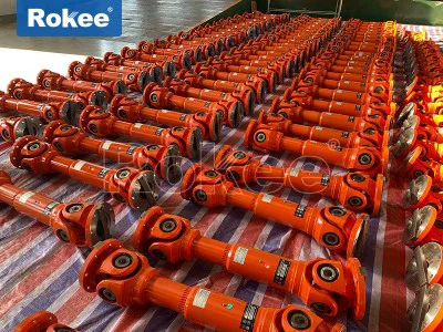
Cardan Shaft Couplings
As a key component in mechanical transmission systems, cardan shaft coupling plays an indispensable role in modern industrial fields. This device, which can connect different axes and achieve power transmission, has undergone continuous technological innovation and application expansion since its inception.
Universal shaft coupling is a mechanical device used to connect different axes and transmit torque and rotational motion. Its core function is to compensate for the angular deviation, radial displacement, and axial displacement between the two axes, so that the driving shaft and the driven shaft can maintain continuous rotation even in the presence of certain deviations. This unique performance makes it an ideal choice for solving complex transmission problems.
From the perspective of kinematic principles, universal couplings work based on multi-body dynamics theory. The master-slave axis rotation angle relationship model established in the right-handed coordinate system shows that the speed ratio relationship between the driving axis rotation angle φ ₁ and the driven axis rotation angle φ ∝ can be expressed as φ ∝/φ ₁=1-sin ² φ ₁ cos ² β. This formula is derived through coordinate transformation in the connected coordinate system and is completely consistent with the results of traditional vector calculation algorithms. When a single cardan shaft coupling is working, if there is an angle β between the two shafts, the angular velocity of the driven shaft will experience periodic fluctuations, and the amplitude of the fluctuations is proportional to the size of the β angle. This fluctuation will generate additional dynamic loads in high-speed transmission, affecting the smoothness of the transmission. To solve this problem, a dual cardan shaft coupling arrangement is commonly used in practical applications, which is designed with an equal angle between the intermediate shaft and the master and slave shafts, and ensures that the two end joints of the intermediate shaft are in the same plane, thereby ensuring stable angular velocity output of the slave shaft.
The core advantage of universal couplings lies in their excellent angle compensation capability. The allowable angle range between the two axes for universal couplings of different structural types is usually between 5 ° and 45 °, depending on the design and application requirements. This ability makes it irreplaceable in situations where installation is difficult or relative displacement occurs during work. Meanwhile, modern universal couplings also have the characteristics of compact structure and high transmission efficiency (up to 98-99.8%), demonstrating significant energy-saving effects in high-power transmission.
From a material perspective, universal couplings are usually made of materials such as 45 steel, 45 forged steel, 40 chromium or cast iron, which have good mechanical properties and wear resistance, and can meet the requirements of different working conditions. As a vulnerable component of universal couplings, the quality and lifespan of bearings directly affect the overall service life of the coupling. Therefore, high-end universal couplings often use special bearing steel and advanced surface treatment technology to extend the bearing lifespan.
After long-term development, universal shaft couplings have formed diverse structural forms, each with its unique advantages and application scenarios. A deep understanding of these structural types and their technical characteristics is crucial for the correct selection and use of universal couplings.
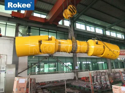
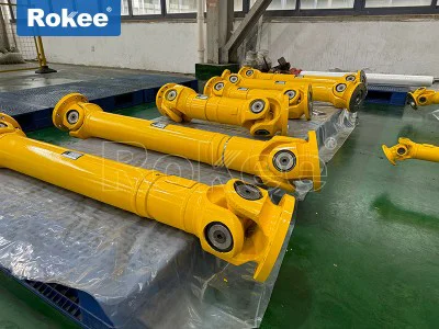
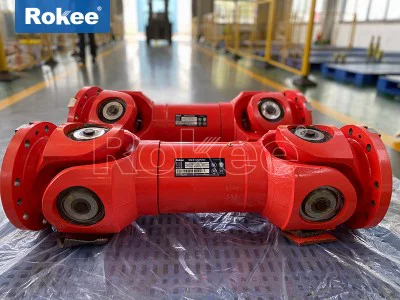
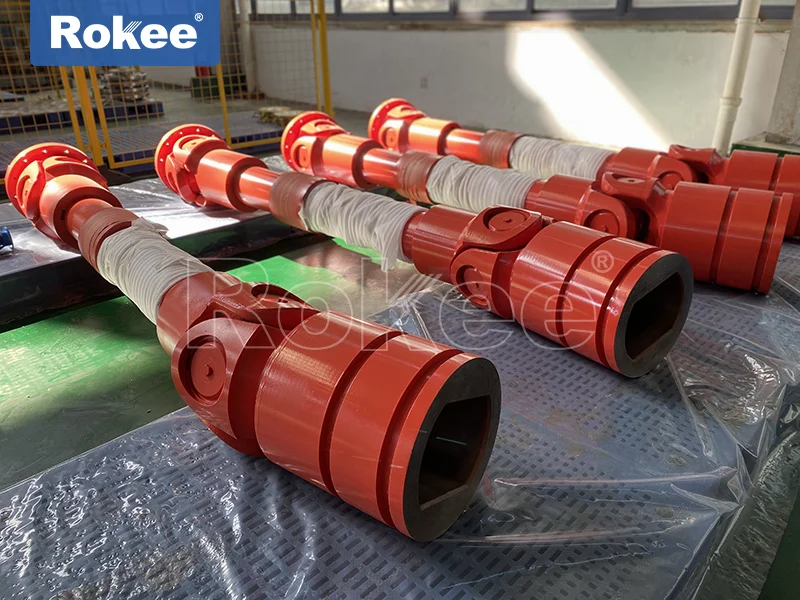
Cross axis cardan shaft coupling is the most common and widely used type. Its core components consist of a cross shaft, bearing sleeve, flange fork, etc., and angle compensation is achieved through the rotation of the cross shaft. According to the different structures of the bearing seat, the cross shaft type is divided into various forms such as SWC type integral fork head type, SWP type partial bearing seat type, and SWZ type integral bearing seat type. Among them, the SWC-BH model adopts an integral fork head design, making operation more reliable. The cross axis cardan shaft coupling has the characteristics of large angle compensation capability (up to 45 °), compact structure, and strong load-bearing capacity, and performs excellently in heavy equipment such as steel rolling machinery, lifting and transportation machinery, and engineering machinery. Compared with other types of couplings with the same rotational diameter, it can transmit greater torque, which is particularly important for mechanical equipment with limited rotational diameter. The SWP-ZG positive flange through type cross shaft cardan shaft coupling improved in 2023 adopts a split bearing seat cover design, which facilitates bearing replacement and makes product maintenance more convenient.
The ball cage cardan shaft coupling (constant velocity cardan shaft coupling) represents a more advanced technological solution. This type of coupling achieves true constant speed transmission through precise coordination of multiple steel balls in the inner and outer raceways, eliminating the speed ratio fluctuation problem of traditional cardan shaft couplings. Ball cage couplings are divided into two categories: fixed and sliding. Fixed couplings come in various forms such as disc, cup, bell, and cylinder. Its typical characteristics are smooth transmission, low noise, and high allowable speed, making it particularly suitable for precision transmission applications. In equipment such as cold rolling lines, shearing lines, and high-speed precision slitting machines, ball cage couplings exhibit excellent performance. The HTJ type ball cage coupling adopts a linear raceway design, which makes axial expansion and installation distance adjustment more convenient. It is widely used in the transmission system of multi roll straightening machines in the petroleum machinery and non-ferrous metal industries.
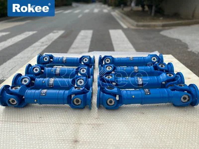
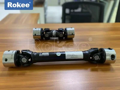
The dual cardan shaft coupling is a composite structure composed of two sets of cardan shaft couplings, which are connected by an intermediate shaft to effectively solve the speed fluctuation problem of a single cardan shaft coupling. The combined double cardan shaft coupling used in cigarette packaging equipment connects the left and right coupling components through a central axis, positioning pins, and locking bolts, significantly reducing maintenance time from 4.5 hours to 1.2 hours and improving equipment maintenance efficiency. The core advantage of the dual cardan shaft coupling lies in its wide range compensation capability, which can support axial/radial composite displacement compensation. The maximum angular displacement compensation is about 40% higher than that of the single cardan shaft coupling, while maintaining the precision and stability of the transmission.
In addition to the main types mentioned above, universal couplings also include various structural forms such as ball fork type, convex block type, ball pin type, ball joint type, and three pin type. According to the magnitude of the transmitted torque, it can be divided into heavy, medium, light, and small; According to the application field, it can be divided into universal and specialized types (such as special couplings for automobiles, agricultural machinery, ships, etc.). With the advancement of materials science and manufacturing technology, new types of universal couplings continue to emerge, such as intelligent universal couplings using composite materials, self-lubricating functions, or integrated sensing functions, providing more diversified choices for various industries.
The correct selection of cardan shaft coupling is a key link to ensure the reliable operation of mechanical transmission systems. Improper selection may lead to premature failure, reduced efficiency, and even safety accidents. The scientific selection process requires comprehensive consideration of multiple factors and adherence to a systematic approach.
Before selecting, a series of prerequisites must be clearly defined: the type, power, and speed characteristics of the prime mover; Is there a deceleration or acceleration device in the transmission system; The nature of the load (constant load, pulsating load, or bidirectional alternating load); Installation status (horizontal, vertical, or tilted, tilt angle size); Working environment (whether there are harsh conditions such as high temperature, dust, water spray, chemical corrosion, etc.); The connection form and specific installation size requirements at both ends of the coupling; Speed range and dynamic balance requirements; Compensation methods for axial dimension errors, etc. These factors together form the basis for selection. For example, in the high-temperature environment of the metallurgical industry, it is necessary to choose high-temperature resistant materials and consider the impact of thermal expansion; In the field of chemical engineering, attention should be paid to the corrosion resistance of couplings.
A cardan shaft coupling, also commonly referred to as a universal shaft coupling, is a critical mechanical transmission component designed to connect two rigid shafts whose axes are inclined to each other or may experience misalignment during operation, enabling the reliable transmission of torque and rotational motion between them. Unlike many other coupling types that require precise coaxial alignment to function effectively, the cardan shaft coupling’s unique structural design allows it to accommodate angular, axial, and radial deviations, making it an indispensable part in a wide range of industrial, automotive, and mechanical systems. Its versatility stems from a combination of thoughtful structural engineering, robust performance characteristics, diverse type variations, and adaptability to various working conditions, all of which work together to meet the complex transmission needs of modern machinery.
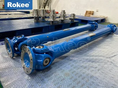
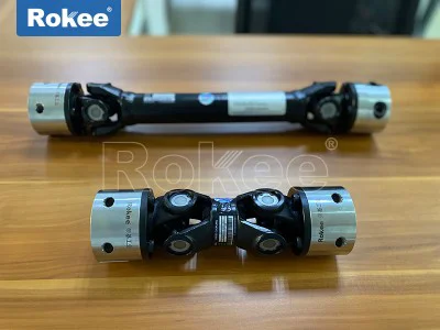
The basic structure of a cardan shaft coupling is relatively straightforward yet ingeniously designed to achieve its primary function of compensating for shaft misalignment while transmitting torque efficiently. At its core, a standard cardan shaft coupling consists of two yokes (also known as forks), a cross shaft (or spider), and bearings. The yokes are typically attached to the ends of the driving and driven shafts, each featuring a pair of ears with holes that accommodate the bearings. The cross shaft, which is the central component, has four cylindrical trunnions—one at each end of its two perpendicular axes—that fit into the bearings mounted in the yokes. This arrangement creates a hinged joint that allows the yokes to rotate relative to each other around the trunnions of the cross shaft, thereby enabling the transmission of rotational motion even when the two connected shafts are not perfectly aligned. The bearings play a crucial role in reducing friction between the cross shaft trunnions and the yoke ears, ensuring smooth rotation and minimizing wear over time; they are usually lubricated to enhance their service life and performance, especially in high-load or high-speed applications. In some cases, the coupling may also include a telescopic section, often in the form of a splined connection between one of the yokes and the shaft, which allows for axial movement to compensate for changes in shaft length due to thermal expansion, vibration, or installation errors. This telescopic feature further enhances the coupling’s adaptability, making it suitable for applications where shaft positions may shift dynamically during operation. The overall structure is designed to be compact, ensuring that it can fit into limited installation spaces while maintaining sufficient strength to transmit the required torque.
The performance of a cardan shaft coupling is defined by a set of key characteristics that determine its suitability for different applications, including angular compensation capability, torque transmission capacity, transmission efficiency, durability, and dynamic stability. One of the most prominent performance features of a cardan shaft coupling is its excellent angular compensation ability, which refers to its capacity to accommodate deviations between the axes of the two connected shafts. Depending on the specific type and design, most cardan shaft couplings can handle angular misalignments ranging from 5° to 45°, with some specialized types capable of accommodating even larger angles. This ability is critical in applications where precise shaft alignment is difficult to achieve, such as in heavy machinery, automotive drivetrains, or agricultural equipment, where structural deflection, installation errors, or dynamic movement can cause shaft misalignment. In addition to angular compensation, many cardan shaft couplings also offer limited radial and axial compensation, allowing them to adapt to minor shifts in shaft position without compromising transmission efficiency or causing excessive stress on the coupling or connected components.
Torque transmission capacity is another vital performance attribute, as it determines the maximum amount of rotational force that the coupling can transmit without failure or excessive deformation. This capacity varies widely depending on factors such as the size of the coupling, the material used in its construction, the design of the yokes and cross shaft, and the quality of the bearings. Cardan shaft couplings are available in a range of sizes, from small, lightweight models capable of transmitting low to moderate torques for precision machinery, to large, heavy-duty models designed to handle extremely high torques in industrial applications such as steel rolling, mining, and marine propulsion. The materials used in manufacturing play a significant role in determining torque capacity and overall durability; common materials include high-strength steel, alloy steel, and sometimes aluminum for lightweight applications. High-strength steel and alloy steel are preferred for heavy-duty applications due to their excellent tensile strength, fatigue resistance, and ability to withstand high loads over extended periods.
Transmission efficiency is also a key performance factor, as it directly impacts the energy efficiency of the entire mechanical system. A high-quality cardan shaft coupling typically exhibits excellent transmission efficiency, often ranging from 98% to 99.8%, meaning that very little energy is lost during the transmission of torque from the driving shaft to the driven shaft. This high efficiency is achieved through the use of low-friction bearings, precise manufacturing tolerances, and a streamlined structural design that minimizes energy losses due to friction, vibration, or misalignment. In contrast to flexible couplings that use elastic elements (which can introduce energy losses), cardan shaft couplings rely on rigid mechanical connections, making them more efficient for high-power transmission applications. This efficiency is particularly important in industrial settings where energy conservation is a priority, as it helps to reduce operational costs and improve the overall performance of the machinery.
Durability and reliability are essential performance characteristics for any mechanical component, and cardan shaft couplings are designed to withstand the harsh conditions often encountered in industrial and automotive applications. The robust construction, high-quality materials, and effective lubrication systems ensure that these couplings can operate reliably for extended periods with minimal maintenance. They are resistant to wear, corrosion, and fatigue, even in environments with high temperatures, dust, moisture, or heavy vibrations. However, their durability can be affected by factors such as improper installation, insufficient lubrication, overloading, or excessive misalignment, which is why proper maintenance and operation are crucial to maximizing their service life. In addition, many cardan shaft couplings are designed with replaceable components, such as bearings and seals, which allows for easy maintenance and reduces the overall cost of ownership.
Dynamic stability is another important performance attribute, especially in high-speed applications. Cardan shaft couplings that are properly balanced exhibit excellent dynamic stability, meaning they operate smoothly without excessive vibration or noise even at high rotational speeds. Vibration can cause premature wear of the coupling components, as well as damage to the connected shafts, bearings, and other mechanical parts, so minimizing vibration is critical for ensuring the long-term reliability of the system. To achieve optimal dynamic stability, cardan shaft couplings are often subjected to precision balancing during manufacturing, which involves adjusting the distribution of mass to eliminate any imbalance that could cause vibration. This balancing process is particularly important for couplings used in high-speed applications such as automotive drivetrains, aircraft systems, and precision machinery, where even minor imbalances can lead to significant performance issues.
Cardan shaft couplings are available in a variety of types, each designed to meet specific application requirements based on factors such as torque capacity, angular misalignment, speed, installation space, and environmental conditions. The most common types include cross shaft cardan couplings, ball cage cardan couplings, ball fork cardan couplings, and telescopic cardan couplings, among others. Each type has its own unique structural features, performance characteristics, and advantages, making them suitable for different scenarios.
The cross shaft cardan coupling, also known as the Hooke’s joint coupling, is the most widely used type of cardan shaft coupling. It features the classic structure of two yokes, a cross shaft, and four bearings, as described earlier. This type of coupling is valued for its simplicity, robustness, high torque capacity, and excellent angular compensation ability. It is commonly used in heavy-duty applications such as steel rolling machinery, mining equipment, cranes, and marine propulsion systems, where it can handle large torques and significant angular misalignments. Cross shaft cardan couplings are available in both single and double configurations; a single cross shaft coupling can accommodate moderate angular misalignments, while a double cross shaft coupling (which consists of two single couplings connected by an intermediate shaft) is used to achieve higher angular compensation or to transmit torque over longer distances. The double configuration also helps to reduce the unevenness of rotational speed that can occur with a single cross shaft coupling, making it suitable for applications where smooth, consistent rotation is required.
Ball cage cardan couplings, also referred to as constant velocity (CV) couplings, are another popular type, known for their ability to transmit torque at a constant angular velocity even when the connected shafts are misaligned. Unlike cross shaft couplings, which can introduce slight variations in rotational speed at high angles of misalignment, ball cage couplings use a set of steel balls held in a cage between an inner and outer race to ensure constant velocity transmission. The inner race is connected to the driving shaft, the outer race to the driven shaft, and the steel balls roll in specially designed grooves in both races, allowing for angular misalignment while maintaining a constant speed ratio. This feature makes ball cage cardan couplings ideal for high-speed, precision applications such as automotive drive shafts, aircraft systems, and precision machinery, where consistent rotational speed is critical. They also offer excellent angular compensation ability, typically up to 45°, and are relatively compact, making them suitable for applications with limited installation space. However, they generally have a lower torque capacity compared to cross shaft couplings, so they are not typically used for heavy-duty applications.
Ball fork cardan couplings are a simpler and more cost-effective alternative to ball cage couplings, featuring a pair of forks with spherical ends that fit into a socket or ball joint. The spherical ends allow for angular misalignment, while the fork design transmits torque from one shaft to the other. This type of coupling is relatively lightweight and compact, making it suitable for low to moderate torque applications such as agricultural machinery, small industrial equipment, and automotive auxiliary systems. However, it has a lower angular compensation capacity compared to cross shaft and ball cage couplings, typically up to 20°, and is not suitable for high-speed or high-precision applications due to potential variations in rotational speed.
Telescopic cardan couplings are designed with a telescopic section, usually a splined connection, that allows for axial movement between the two shafts. This section consists of a splined shaft that fits into a splined sleeve, enabling the coupling to expand or contract to compensate for axial displacement caused by thermal expansion, vibration, or installation errors. Telescopic cardan couplings are commonly used in applications where the distance between the two shafts may change during operation, such as in automotive drivetrains, construction machinery, and steel rolling equipment. They can be combined with other types of cardan couplings, such as cross shaft or ball cage couplings, to provide both angular and axial compensation. The telescopic feature also makes installation easier, as it allows for some adjustment in the shaft length during assembly. In addition to these common types, there are also specialized cardan shaft couplings designed for specific applications, such as three-pin couplings for large angular misalignments, convex block couplings for high radial loads, and ball joint couplings for precision applications.
The wide range of structural designs and performance characteristics of cardan shaft couplings makes them suitable for a diverse array of applications across various industries. One of the most common applications is in the automotive industry, where cardan shaft couplings are used in drivetrains to connect the transmission to the differential, especially in rear-wheel-drive and four-wheel-drive vehicles. In these applications, the coupling must accommodate angular misalignment between the transmission and differential, which can change during vehicle operation due to suspension movement, and transmit high torques efficiently. Ball cage cardan couplings are often used in modern automotive drive shafts due to their constant velocity transmission, which ensures smooth operation at high speeds, while cross shaft couplings may be used in heavier vehicles such as trucks and buses for their higher torque capacity. Telescopic cardan couplings are also commonly used in automotive applications to compensate for axial displacement caused by thermal expansion and suspension movement.
The industrial sector is another major user of cardan shaft couplings, with applications in a wide range of heavy machinery and equipment. In the metallurgical industry, for example, cardan shaft couplings are used in steel rolling mills to connect the motors to the rolling stands, where they must handle extremely high torques and accommodate angular misalignment caused by the heavy loads and thermal expansion of the equipment. Cross shaft cardan couplings are particularly well-suited for this application due to their high torque capacity and robustness. In the mining industry, cardan shaft couplings are used in crushers, conveyors, and other heavy equipment, where they must withstand harsh environmental conditions, high loads, and significant misalignment. They are also used in cranes and hoists to transmit torque from the motor to the lifting mechanism, ensuring smooth and reliable operation.
The construction machinery industry also relies heavily on cardan shaft couplings, with applications in excavators, loaders, bulldozers, and other equipment. In these applications, the couplings must accommodate large angular misalignments caused by the articulation of the machinery and transmit high torques to power the various components, such as the hydraulic pumps, wheels, and excavator arms. Telescopic cardan couplings are often used in construction machinery to compensate for axial displacement caused by the dynamic movement of the equipment, while cross shaft couplings are used for their high torque capacity and durability. The agricultural industry uses cardan shaft couplings in a variety of equipment, including tractors, harvesters, and irrigation systems. In these applications, the couplings must be lightweight, compact, and able to withstand outdoor environmental conditions, such as dust, moisture, and temperature variations. Ball fork cardan couplings are commonly used in agricultural machinery due to their simplicity and cost-effectiveness, while cross shaft couplings may be used in heavier agricultural equipment.
Aerospace and aviation applications also utilize cardan shaft couplings, albeit in more specialized forms. In aircraft systems, for example, cardan shaft couplings are used in engines, propellers, and control systems, where they must meet strict performance requirements for weight, precision, and reliability. Ball cage cardan couplings are often used in these applications due to their constant velocity transmission, high-speed stability, and compact design. They must be manufactured to extremely tight tolerances to ensure optimal performance and safety in the harsh aerospace environment, which includes high temperatures, high pressures, and significant vibrations.
Precision machinery and robotics are another area where cardan shaft couplings are increasingly being used. In robotics, for example, cardan shaft couplings are used in joint mechanisms to transmit torque and motion while accommodating angular misalignment between the motor and the joint. They must be compact, lightweight, and precise to ensure smooth and accurate movement of the robot arm. Ball cage cardan couplings are often preferred for these applications due to their high precision and constant velocity transmission. In precision machining equipment, such as lathes, milling machines, and grinders, cardan shaft couplings are used to connect the motor to the spindle, where they must transmit torque efficiently and maintain precise rotational speed to ensure the quality of the machined part.
Marine applications also utilize cardan shaft couplings, particularly in ship propulsion systems. In these systems, the coupling connects the marine engine to the propeller shaft, where it must handle extremely high torques and accommodate angular misalignment caused by the movement of the ship and the flexing of the hull. Cross shaft cardan couplings are commonly used in marine applications due to their high torque capacity and robustness, while telescopic couplings may be used to compensate for axial displacement caused by thermal expansion and hull flexing. The marine environment is particularly harsh, with high levels of moisture, salt, and corrosion, so cardan shaft couplings used in marine applications are often made from corrosion-resistant materials and equipped with specialized seals to protect the internal components.
In addition to these major industries, cardan shaft couplings are also used in a variety of other applications, including power generation, where they are used in wind turbines and other power generation equipment to connect the generator to the turbine; material handling, where they are used in conveyors, elevators, and other equipment; and household appliances, such as washing machines and dryers, where they are used in the drive systems. The versatility of cardan shaft couplings is further enhanced by their ability to be customized to meet specific application requirements, such as custom sizes, materials, and performance characteristics. Manufacturers can tailor the design of the coupling to accommodate specific torque capacities, angular misalignments, speeds, and environmental conditions, making it possible to use cardan shaft couplings in even the most specialized applications.
In conclusion, the cardan shaft coupling is a versatile and essential mechanical transmission component that plays a critical role in a wide range of industrial, automotive, aerospace, and agricultural applications. Its unique structural design, which consists of yokes, a cross shaft, and bearings, enables it to accommodate angular, axial, and radial misalignments while transmitting torque efficiently and reliably. The key performance characteristics, including angular compensation ability, torque transmission capacity, transmission efficiency, durability, and dynamic stability, make it suitable for diverse working conditions, from low-speed, low-torque precision applications to high-speed, high-torque heavy-duty applications. The various types of cardan shaft couplings, such as cross shaft, ball cage, ball fork, and telescopic couplings, each offer distinct advantages and are tailored to specific application requirements, further expanding the versatility of this component. As modern machinery becomes more complex and demands higher performance, the cardan shaft coupling continues to evolve, with advancements in materials, design, and manufacturing techniques improving its performance, durability, and efficiency. Whether in a heavy steel rolling mill, a high-performance sports car, a precision robot, or a small agricultural tractor, the cardan shaft coupling remains an indispensable part of the mechanical transmission system, ensuring the smooth and reliable operation of the machinery it serves.