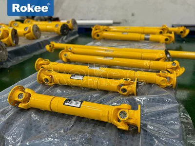
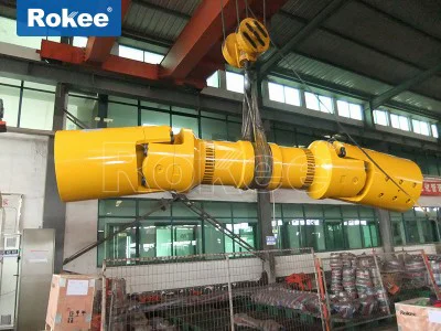
Telescoping Driveshafts
The telescoping driveshaft as a key component in mechanical transmission systems, plays an irreplaceable role in various industrial equipment and automotive transmission systems. It solves the power transmission problem caused by distance changes and angle offsets in the transmission system through unique design.
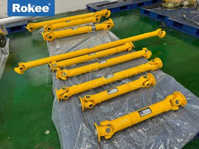
As a core component in modern mechanical transmission systems, telescoping driveshafts play an irreplaceable role in fields such as automobiles, engineering machinery, and industrial equipment. It solves complex mechanical problems caused by positional changes during power transmission through clever structural design, achieving efficient and stable power transmission.
A telescoping driveshaft is a mechanical device that can adjust its length to adapt to changes in the distance between connecting components, while transmitting torque. In the power transmission system, it plays the role of an "energy transporter", responsible for transmitting the power generated by the prime mover (such as the engine, electric motor) to the actuator (such as the wheels, working devices). The reason why the transmission shaft needs to be designed as a scalable structure is mainly to solve the connection problem caused by relative position changes during the operation of the mechanical system. For example, in industrial equipment, thermal expansion or mechanical displacement can also change the relative position between transmission components. If there is no telescopic adjustment function, this position change will cause stress concentration in the transmission system, and even damage to components.
The working principle of the telescoping driveshaft is based on the synergistic effect of several key mechanical principles. When the power generated by the engine or electric motor is output through the gearbox, it is first transmitted to the input end of the drive shaft. The transmission shaft achieves axial expansion and contraction through its internal spline connection structure, which allows the shaft to freely slide within a certain range in the length direction while transmitting rotational torque. At the same time, the universal joint component installed on the transmission shaft solves the problem of angle deviation, and it can effectively transmit power even when there is an angle between the two axis lines (usually up to 15-30 degrees, depending on the specific design). This angle compensation capability is particularly important for vehicles driving on bumpy roads or industrial equipment operating under non centering conditions.
In the process of power transmission, the transmission shaft needs to withstand various composite loads. In addition to the main torsional stress, it is also affected by bending stress, vibration load, and impact load. Especially during rapid acceleration or heavy load starting of the vehicle, the transmission shaft will experience instantaneous high torque impact. In order to cope with these complex working conditions, modern telescoping driveshafts are usually made of high-strength alloy steel and undergo precision heat treatment processes to improve their fatigue life.
It is worth noting that as a high-speed rotating body, the dynamic balance performance of the transmission shaft directly affects the smoothness of the entire transmission system. Experimental data shows that when the unbalance of the transmission shaft exceeds 100g · cm, significant vibration and noise will be generated during high-speed operation. Therefore, high-quality telescoping driveshafts undergo strict dynamic balance testing and adjustment before leaving the factory, usually requiring residual unbalance to be controlled within 30g · cm to ensure smooth and comfortable driving of the vehicle. This precise balancing performance is particularly important for high-end automobiles and precision industrial equipment, and is also one of the important indicators to measure the level of transmission shaft manufacturing technology.
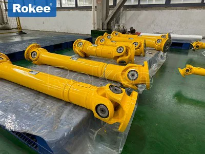
The brilliance of the telescoping driveshaft lies in its modular structural design, where each component undertakes a unique and critical function. A deep understanding of the construction and working principles of these components is crucial for the proper use and maintenance of the drive shaft. A complete telescoping driveshaft system mainly consists of three core components: shaft tube, telescopic sleeve, and universal joint. Each component also includes several precision designed sub components, which together constitute this efficient power transmission mechanism.
As the "skeleton" of the transmission shaft, the shaft tube undertakes the dual task of transmitting torque and supporting the overall structure. The shaft tube of modern transmission shafts generally adopts a hollow design, which can significantly reduce weight while ensuring sufficient torsional stiffness. According to different application scenarios, the manufacturing process and materials of the shaft tube also vary. For ordinary passenger cars, the axle tube is usually made of high-quality carbon steel sheet rolled and welded with a thickness of 1.5-3mm; The transmission shafts of heavy trucks and construction machinery are often made of seamless steel pipes or alloy steel forging processes to cope with larger loads.
The telescopic sleeve is a key component for adjusting the length of the transmission shaft, and its design directly affects the reliability and service life of the transmission system. The traditional telescopic sleeve adopts a rectangular tooth spline structure, while modern designs generally use high pressure angle involute short tooth splines. This improvement increases the tooth root thickness by about 30% and significantly improves the load-bearing capacity. A more advanced design has coated the entire spline tooth surface with a special nylon coating (usually 0.1-0.3mm thick), which not only reduces the friction coefficient by about 45%, but also endows the spline pair with self-lubricating properties, greatly improving wear resistance.
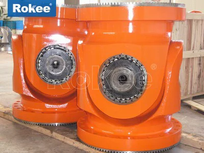
As the most precise component in the transmission shaft, the universal joint is responsible for solving angle compensation problems. According to different structural principles, universal joints can be divided into various types, with the most common being cross axis universal joints and cage type constant velocity universal joints. The cross axis universal joint consists of a cross axis, four needle roller bearings, and two universal joint forks. It has a simple and reliable structure and is widely used in commercial vehicles and rear wheel drive passenger cars. The core component, the cross shaft, is usually made of carburizing alloy steel such as 20CrMnTi, with a surface hardness of HRC58-62, while the core maintains good toughness. The needle roller bearings are made of high-quality bearing steel (such as GCr15) and equipped with multi lip rubber oil seals (some with skeleton reinforcement) to ensure that the lubricating grease does not leak and that pollutants do not invade. Tests have shown that a well-designed cross axis universal joint can have a service life of over 200000 kilometers under normal operating conditions.
In addition to these three core components, the transmission shaft system also includes some auxiliary components, such as intermediate support bearings, dynamic balance plates, protective covers, etc. The intermediate support bearing is used to support the multi-stage transmission shaft of long wheelbase vehicles, usually designed with rubber damping, which can withstand radial loads and absorb vibration and noise. The dynamic balance plate is a small metal piece used to adjust the balance state of the transmission shaft. After precise calculation, it is welded at a specific position on the shaft tube, and the balance accuracy can reach less than 1g. These seemingly insignificant auxiliary components actually have a significant impact on the overall performance and service life of the transmission shaft.
telescoping driveshafts can be classified into multiple types based on different classification criteria, each with its unique structural characteristics and applicable scenarios. Understanding these classifications not only helps in selecting transmission shafts correctly, but also enables a better understanding of their application principles in various types of mechanical equipment. The technological evolution of transmission shafts reflects the relentless pursuit of efficient power transmission solutions in the field of mechanical engineering. From simple rigid connections to precise constant speed transmission, transmission shaft technology has developed into a specialized engineering discipline.
According to the elastic characteristics of universal joints, transmission shafts can be divided into two categories: rigid universal joint transmission shafts and flexible universal joint transmission shafts. The rigid universal joint transmission shaft relies on the hinge type connection of parts to transmit power, and has the characteristics of simple structure and high transmission efficiency (usually up to 98-99%), making it the preferred choice for most commercial vehicles and industrial equipment. Among them, the cross axis universal joint is the most typical representative, which consists of a cross axis and four needle roller bearings, and can adapt to angle changes of 15-25 degrees. Flexible universal joints use elastic components such as rubber and polyurethane to transmit torque, which has the advantages of buffering, vibration reduction, and absorbing installation errors. However, the transmission efficiency is slightly lower (about 92-95%), and the load-bearing capacity is relatively small. This type of universal joint is commonly used in situations that require high vibration control, such as generator sets, precision machinery, etc., and its maximum allowable angle usually does not exceed 10 degrees.
According to the characteristics of angular velocity, transmission shafts can be classified into three types: non constant velocity universal joints, quasi constant velocity universal joints, and constant velocity universal joints. The output shaft speed of non-uniform universal joints (represented by the cross shaft type) will fluctuate periodically during the transmission process, and the fluctuation amplitude increases with the increase of the angle between the shafts. Theoretical calculations show that when the angle is 10 degrees, the velocity fluctuation is about 3%; When the angle increases to 30 degrees, the fluctuation will be as high as 13.4%. This kind of fluctuation will generate additional dynamic loads in the transmission system, so double universal joint arrangements are commonly used in engineering, and speed fluctuations are eliminated by placing the two universal joint forks in the same plane and at equal angles. Quasi constant velocity universal joints (such as double joint and three pin shaft) reduce speed fluctuations through special structural design and can achieve approximate constant velocity transmission under specific conditions.
In the realm of mechanical power transmission, the telescoping driveshaft stands as a versatile and indispensable component, engineered to address the inherent challenges of variable shaft distances, angular misalignment, and dynamic operational movements that rigid drive shafts cannot resolve. Unlike fixed-length drive shafts that rely on precise, unchanging alignment between driving and driven components, telescoping driveshafts integrate a sliding, adjustable core that enables axial length variation while maintaining consistent torque delivery and rotational stability. This unique design has cemented their role across countless industrial, automotive, agricultural, and heavy machinery applications, where adaptability, durability, and reliable power transfer are non-negotiable.
At its core, the telescoping driveshaft is a precision-engineered assembly built around a modular, sliding mechanism, paired with components that facilitate angular flexibility and robust torque transmission. The primary structural elements work in tandem to balance adjustability, strength, and operational smoothness, with each part serving a targeted purpose in the overall functionality. The central feature enabling telescopic action is the sliding spline assembly, typically consisting of a male splined shaft and a female splined sleeve that interlock with precision-machined teeth or profiles. This spline interface is the heart of the shaft’s adjustability, allowing linear axial movement while transferring rotational force without slippage or power loss. Common spline profiles include parallel-sided splines, involute splines, and hexagonal or square profiles, each selected based on torque demands, precision requirements, and cost considerations; involute splines, for instance, offer higher load-bearing capacity and smoother sliding motion, making them ideal for heavy-duty applications, while simpler square or hex profiles serve cost-effective, light-duty setups effectively.
Surrounding the spline assembly, the driveshaft features outer shaft tubes or solid shaft segments that provide structural rigidity and protect internal components from environmental contaminants, mechanical damage, and premature wear. These outer shafts are often constructed from high-strength alloy steels, chosen for their exceptional tensile strength, fatigue resistance, and ability to withstand repeated stress from rotation, vibration, and telescopic movement. In some lightweight or high-performance applications, advanced composite materials may be used to reduce rotational inertia without compromising structural integrity, though metallic alloys remain the standard for most heavy-duty and industrial uses. To complement the axial adjustability of the spline section, nearly all telescoping driveshafts incorporate universal joint assemblies at one or both ends, which accommodate angular misalignment between the driving and driven shafts. These universal joints, often designed as single or double cardan joints, allow the shaft to operate efficiently even when the connected components are not perfectly collinear, handling moderate to significant angular offsets while maintaining uniform rotational speed and minimizing vibration. Double cardan joints are particularly effective for reducing non-uniform velocity issues common in single universal joints, enhancing smoothness at higher operating speeds.
Additional critical structural components include bearing supports, sealing systems, and lubrication pathways, all of which are vital for sustaining long-term performance. Bearing assemblies, typically needle roller bearings or heavy-duty roller bearings, reduce friction between rotating and stationary parts, supporting radial and axial loads generated during operation and preventing premature wear on the spline and universal joint components. Sealing elements, such as lip seals, dust boots, and protective gaskets, create a barrier against dirt, moisture, debris, and corrosive substances that could infiltrate the spline assembly or universal joints, causing abrasion, rust, or lubrication degradation. Proper lubrication is equally essential, with dedicated channels or reservoirs delivering high-temperature, high-viscosity lubricants to the spline interface and bearing surfaces to minimize friction, dissipate heat, and extend the service life of moving parts. Together, these structural components form a cohesive unit that merges telescopic flexibility with mechanical robustness, creating a drive shaft that can adapt to dynamic conditions while delivering consistent power transmission.
The performance characteristics of telescoping driveshafts are defined by a set of core attributes that determine their suitability for specific applications, with each attribute optimized based on design intent and operating environment. Foremost among these is axial adjustability range, which dictates the maximum and minimum length the shaft can achieve during operation or installation. This range is engineered to match the expected movement of connected components—whether it is the suspension travel of a vehicle, the shifting position of industrial machinery, or the variable spacing between agricultural implements—and must balance sufficient travel with structural stability, as excessive adjustability can compromise torsional rigidity. Torsional strength and torque capacity are equally critical, representing the shaft’s ability to transmit rotational force without deformation, twisting, or failure. This performance metric is dictated by material selection, spline profile, shaft diameter, and heat treatment processes, with heavy-duty variants engineered to handle extreme torque loads in construction, mining, and marine applications, while light-duty versions prioritize compactness and efficiency for smaller machinery.
Operating speed and rotational smoothness are key performance factors for applications involving high-speed power transmission, such as automotive drivetrains or industrial conveyor systems. High-quality telescoping driveshafts are designed to minimize vibration, noise, and non-uniform rotation, even at elevated speeds, through precision balancing, optimized universal joint geometry, and tight-tolerance spline machining. Misalignment tolerance is another defining performance trait, referring to the shaft’s ability to accommodate angular, parallel, or radial misalignment between driving and driven components without sacrificing power transfer or accelerating wear. This tolerance is largely governed by the design of the universal joint assemblies, with heavy-duty models capable of handling significant angular offsets to suit rugged, uneven operating conditions. Durability and wear resistance round out the core performance metrics, reflecting the shaft’s ability to withstand prolonged use, repetitive telescopic movement, and harsh environmental factors such as temperature extremes, moisture, and abrasive materials. Enhanced durability is achieved through specialized heat treatments, surface coatings, and hardened spline surfaces, which resist scuffing, pitting, and fatigue cracking over extended service life.
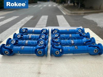
Telescoping driveshafts are not a one-size-fits-all solution; instead, they are classified into distinct types based on structural design, operational functionality, and intended use cases, each engineered to excel in specific conditions. The broadest classification differentiates between **single-telescoping driveshafts** and **multi-telescoping driveshafts**, defined by the number of sliding spline sections integrated into the assembly. Single-telescoping models feature one central spline joint, providing a moderate range of axial adjustment and serving as the most common and cost-effective variant for standard applications where limited length variation is needed. These shafts are compact, lightweight, and easy to install, making them ideal for passenger vehicles, light industrial machinery, and small agricultural equipment. Multi-telescoping driveshafts, by contrast, incorporate two or more nested spline sections, delivering an extended range of length adjustment to accommodate large axial movements. These are reserved for heavy-duty, specialized applications such as large construction machinery, commercial trucks with extended wheelbases, and marine propulsion systems, where significant spacing changes between components occur during operation.
Another key classification is based on the type of universal joint integration, separating telescoping driveshafts into **single universal joint telescoping shafts** and **double universal joint telescoping shafts**. Single universal joint variants offer basic angular misalignment compensation and are suited for low-to-moderate speed applications with mild misalignment, such as small agricultural implements and light industrial pumps. They are simpler in design and more affordable, though they may exhibit minor speed fluctuations at higher rotational speeds. Double universal joint telescoping driveshafts, also known as constant-velocity telescoping shafts, feature dual cardan joints that eliminate non-uniform rotational velocity, delivering smoother power transfer at higher speeds and accommodating larger angular offsets. These are preferred for high-performance automotive applications, heavy industrial machinery, and precision equipment where vibration and speed inconsistency would compromise operational efficiency or component longevity.
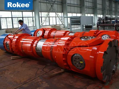
Telescoping driveshafts can also be categorized by their structural rigidity and intended load capacity, distinguishing between **light-duty**, **medium-duty**, and **heavy-duty** variants. Light-duty telescoping driveshafts are constructed with thinner-walled shaft tubes, smaller spline profiles, and basic universal joints, designed for low-torque, low-speed applications such as small garden machinery, portable power equipment, and light automotive accessories. They prioritize compactness and cost efficiency over extreme durability, making them suitable for non-demanding, occasional use. Medium-duty driveshafts strike a balance between strength and versatility, featuring reinforced alloy steel construction, medium-capacity splines, and durable universal joints, catering to a wide range of general industrial applications, commercial light trucks, and mid-sized agricultural machinery. Heavy-duty telescoping driveshafts are built for extreme operating conditions, with thick, hardened alloy steel shafts, large involute splines, heavy-duty double universal joints, and reinforced sealing and lubrication systems. These shafts are engineered to handle massive torque loads, constant heavy use, and harsh environments, serving critical roles in construction equipment, mining machinery, large agricultural harvesters, marine vessels, and heavy commercial vehicles.
A final classification distinguishes between **stationary telescoping driveshafts** and **dynamic telescoping driveshafts**, based on whether length adjustment occurs during installation or active operation. Stationary telescoping shafts are adjusted to a fixed length during assembly and remain static during use, primarily serving to simplify installation by accommodating minor spacing variations between components. Dynamic telescoping shafts, the more prevalent type, adjust their length continuously during operation to compensate for real-time movements, such as suspension compression and extension in vehicles, arm articulation in construction machinery, or positional shifts in industrial processing lines. This dynamic adaptability is what makes telescoping driveshafts irreplaceable in applications where component positions are not fixed.
The unique combination of axial adjustability, angular flexibility, and robust torque transmission makes telescoping driveshafts integral to a vast array of industries, with each sector leveraging their specific capabilities to overcome operational challenges. In the automotive and transportation sector, telescoping driveshafts are a cornerstone of vehicle drivetrains, particularly in rear-wheel-drive and four-wheel-drive models, commercial trucks, buses, and off-road vehicles. In these applications, they compensate for the vertical movement of rear suspension systems, maintaining consistent power delivery from the transmission to the drive axle as the vehicle navigates uneven terrain, bumps, or load changes. Off-road vehicles and all-terrain vehicles rely heavily on dynamic telescoping driveshafts to handle extreme suspension travel, ensuring the drivetrain remains intact and functional even in rugged, off-pavement conditions. For commercial trucks with variable wheelbases or trailer attachments, telescoping driveshafts adapt to changes in vehicle length, ensuring reliable power transfer regardless of configuration.
The agricultural industry is another major adopter of telescoping driveshafts, where they are essential for powering a wide range of farm implements and machinery. Tractors, harvesters, plows, mowers, and balers all utilize telescoping power take-off (PTO) driveshafts to connect the tractor’s PTO shaft to attached implements, accommodating variable spacing between the tractor and implement as equipment is attached, adjusted, or operated across uneven farmland. These driveshafts must withstand dusty, moist, and abrasive agricultural environments, as well as frequent attachment and detachment, making durable sealing and wear-resistant splines critical for longevity. Their ability to telescope simplifies implement swaps, reducing downtime and improving operational efficiency on farms of all sizes.
In the construction and heavy machinery sector, telescoping driveshafts play a vital role in powering excavators, loaders, cranes, bulldozers, and concrete mixers, where articulated arms, moving booms, and adjustable chassis create constant changes in component spacing. Heavy-duty telescoping driveshafts transmit high torque from engines to hydraulic pumps, wheels, and working attachments, even as machinery articulates and shifts position. They withstand heavy loads, constant vibration, and harsh construction site conditions, including dirt, debris, and extreme temperatures, ensuring uninterrupted operation in demanding job sites. Without telescoping driveshafts, the dynamic movement and functionality of modern construction equipment would be severely limited.
Industrial manufacturing and material handling also rely heavily on telescoping driveshafts for a variety of stationary and mobile machinery. Conveyor systems, packaging lines, milling machines, drilling equipment, and assembly line machinery use these driveshafts to transfer power between motors and driven components, accommodating minor misalignment, thermal expansion, and positional adjustments during production. In industrial settings, precision and operational smoothness are paramount, making double universal joint telescoping driveshafts a popular choice for high-speed manufacturing equipment, as they minimize vibration and maintain consistent rotational speed. They are also used in industrial pumps, compressors, and generators, where flexible power transmission ensures reliable operation even as components shift or expand due to heat and movement.
Beyond these core sectors, telescoping driveshafts find specialized applications in marine equipment, aerospace ground support machinery, mining equipment, and recreational vehicles. Marine propulsion systems use waterproofed telescoping driveshafts to transfer power from engines to propellers, adapting to the movement of boat hulls and accommodating variable shaft lengths in different vessel designs. Mining machinery relies on heavy-duty, abrasion-resistant telescoping driveshafts to operate in harsh underground conditions, where dust, rock, and extreme loads demand maximum durability. Recreational vehicles, such as golf carts, ATVs, and small boats, use compact light-duty telescoping driveshafts for efficient power transfer and adaptability in small-scale applications.
As mechanical engineering continues to evolve, the design and performance of telescoping driveshafts are constantly improving, with advancements in material science, precision manufacturing, and surface engineering enhancing their durability, efficiency, and adaptability. Modern iterations feature lightweight yet strong materials, low-friction spline coatings, and improved sealing technologies that reduce maintenance needs and extend service life, even in the harshest operating environments. The core value of telescoping driveshafts remains unchanged, however: their ability to merge adjustable length with reliable torque transmission fills a critical gap in power transmission systems, solving challenges that rigid drive shafts cannot address. From small-scale agricultural tools to massive industrial and construction machinery, telescoping driveshafts prove their worth daily, enabling the smooth, efficient, and reliable operation of equipment across countless sectors. Their versatility, durability, and functional adaptability ensure they will remain a foundational component in mechanical power transmission for years to come, evolving alongside technological advancements to meet the ever-growing demands of modern industry and transportation.