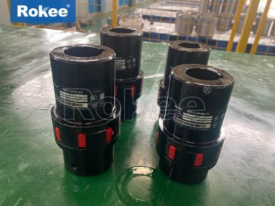
Claw Type Flexible Couplings
Claw type flexible coupling is a widely used type of elastic coupling in mechanical transmission systems. It connects shafts through a special "claw" design and has the ability to compensate for axial, radial, and angular deviations. This type of coupling is widely used in various industrial equipment due to its simple structure, easy installation, and low maintenance cost.
Compared with traditional rigid couplings, the most significant feature of claw type flexible couplings is that they can absorb and buffer vibrations and impacts caused by misalignment while transmitting torque, protecting other components in the transmission system from damage. Its unique flexible component design makes it perform well in medium torque transmission scenarios, especially suitable for working environments that require some elastic compensation.
A typical claw type flexible coupling consists of the following key components:
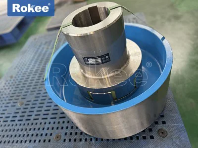
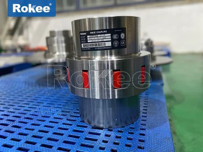
Metal wheel hub (claw plate): usually made of cast iron, steel or aluminum alloy material, with interlocking "claw" shaped structures on both sides, it is the main component for transmitting torque
Elastic element (buffer block): located between the two wheel hub teeth, mostly made of polymer materials such as polyurethane, rubber, or nylon, providing flexibility and cushioning effect
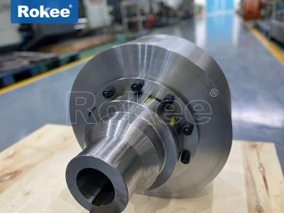
Connecting bolts and nuts: used to fix the two halves of the coupling and apply preload force
Protective cover (optional): Some models are equipped with protective covers to prevent foreign objects from entering and ensure safe operation
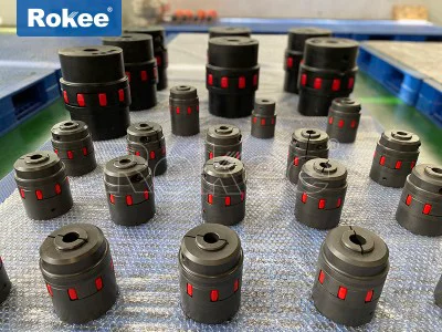
The core technology of claw coupling lies in its claw shaped meshing structure. Usually, there are 6-12 evenly distributed claw teeth on each wheel hub, which present a special arc-shaped or trapezoidal profile to ensure uniform stress distribution when transmitting torque. The claws of the two halves of the coupling are arranged in a staggered manner, and a non rigid connection is achieved through an elastic element in the middle.
This design allows for the existence of:
Axial displacement compensation: ± 0.5-3mm
Radial deviation compensation: 0.2-1.5mm
Angular deviation compensation: 0.5 ° -3 °
The material properties of the buffer block, as the core flexible component of the claw coupling, directly affect the performance of the coupling
Polyurethane (PU): The most common material with good wear resistance, tear resistance, and moderate elastic modulus, working temperature range of -30 ℃ to+80 ℃
Nitrile rubber (NBR): Good oil resistance, suitable for occasions with lubricating oil environment
Hytrel (polyester elastomer): High strength, fatigue resistant, suitable for high-speed applications
Nylon (PA): High rigidity, suitable for situations requiring high torsional stiffness
The elastic elements of different materials endow the coupling with different stiffness characteristics, and users can choose the appropriate type according to specific working conditions.
Claw type flexible couplings transmit torque through the compression deformation of elastic elements. When the driving shaft rotates, the claws of the driving hub push the elastic element, which then transmits the force to the claws of the driven hub, thereby achieving torque transmission. During this process, the elastic element is always in a compressed state rather than a shear state, which allows the claw coupling to withstand larger impact loads.
The ability of claw couplings to compensate for shaft system deviations comes from the deformability of elastic elements and the design of clearances between claw teeth
Axial compensation: When there is axial displacement between the two axes, the elastic element can compress or extend axially between the claw teeth
Radial compensation: The radial deformation ability of elastic elements allows for a certain center deviation between the two axes
Angular compensation: The change in angle between the claw teeth causes uneven compression of the elastic element, achieving absorption of angular deviation
It is worth noting that any form of deviation can cause additional stress on the elastic element, so in practical applications, the misalignment should be minimized as much as possible to extend the life of the coupling.
The elastic elements of claw couplings have significant damping characteristics, which can effectively absorb and attenuate vibrations transmitted from the prime mover (such as a motor) or load end. This feature is particularly suitable for:
Suppress torsional vibration during motor start-up
Reduce impact loads in gearboxes or transmission chains
Reduce the noise level of the entire transmission system
When choosing a claw type flexible coupling, the following main technical parameters need to be considered:
Rated torque Tn: The maximum torque that the coupling can continuously transmit (N · m)
Maximum torque Tk: the peak torque that can be sustained in the short term (usually about 2-3 times the rated torque)
Allowable speed n: the maximum working speed (rpm) related to the size and balance level of the coupling
Torsional stiffness: reflects the ability of the coupling to resist torsional deformation (N · m/rad)
Moment of inertia: an important parameter affecting the acceleration performance of the system (kg · m ²)
Working temperature range: depends on the elastic element material (usually -30 ℃ to+80 ℃)
The key to ensuring the long-term reliable operation of the coupling lies in correct installation:
Cleaning inspection: Clean the shaft end and coupling inner hole, check for damage
Centering adjustment: use a dial indicator or a laser centering instrument for accurate centering, and control the deviation within the allowable range
Assembly of wheel hub: Use appropriate methods (hot installation or hydraulic tools) to install the wheel hub onto the shaft
Install elastic components: Install buffer blocks according to the marked positions to ensure uniform distribution
Connect the two halves of the coupling: alternately and evenly tighten the connecting bolts to the specified torque
Final inspection: manually rotate to check for any jamming, and perform dynamic balancing if necessary
Although claw couplings are low maintenance products, regular inspections are still essential:
Visual inspection: Check the elastic components monthly for cracks, permanent deformation, or wear
Bolt inspection: Check the tightening status of bolts every 3-6 months to prevent loosening
Re check the alignment after major equipment repairs or abnormal vibrations
Lubrication: Some models require regular lubrication of the claw tooth contact surface (using specified grease)
Claw type flexible couplings are widely used in various industrial equipment:
Pump equipment: centrifugal pump, plunger pump, vacuum pump, etc
Fan system: centrifugal fan, axial flow fan, blower
Compressor: screw type, reciprocating air compressor
Conveyor machinery: conveyor belts, elevators, mixing equipment
Claw type flexible couplings, as an economical and practical mechanical transmission component, occupy an important position in the industrial field due to their excellent comprehensive performance. With the application of new materials and technologies, their performance will be further improved and their application scope will continue to expand. Proper selection, installation, and maintenance of claw type flexible couplings can significantly improve the reliability and service life of mechanical transmission systems, creating greater value for enterprises.
In the field of mechanical power transmission, couplings serve as essential components that bridge rotating shafts, enabling the efficient transfer of torque while accommodating inevitable misalignments, absorbing shocks, and reducing vibrations. Among the diverse range of couplings available, the claw type flexible coupling stands out for its simplicity, cost-effectiveness, and versatility, making it a widely used choice in various industrial and commercial applications. Unlike rigid couplings that require precise alignment and offer no flexibility, claw type flexible couplings leverage the elasticity of their components to balance torque transmission efficiency with the ability to mitigate the negative impacts of shaft misalignment and operational vibrations.
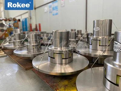
The fundamental structure of a claw type flexible coupling is relatively straightforward yet ingeniously designed to fulfill its core functions of torque transmission, deviation compensation, and vibration damping. Typically, it consists of three main components: two metal hubs with claw-shaped projections (often referred to as jaw plates) and an intermediate elastic element (commonly known as a spider or cushion block) that fits snugly between the claws of the two hubs. The metal hubs are the primary torque-transmitting components, usually fabricated from high-strength materials such as cast iron, carbon steel, aluminum alloy, or in special cases, stainless steel. The choice of material for the hubs depends on the specific application requirements, including torque capacity, operating temperature, and environmental conditions. For instance, aluminum alloy hubs are preferred in applications where weight reduction is critical, such as in small precision equipment, while carbon steel or cast iron hubs are used for heavy-duty applications that demand higher torque-bearing capacity. The claw-shaped projections on the hubs are evenly spaced around the circumference, typically ranging from 6 to 12 claws per hub, and feature a special arc-shaped or trapezoidal profile to ensure uniform stress distribution during torque transmission. The claws of the two hubs are arranged in a staggered manner, creating a space for the elastic element to be inserted, which forms a non-rigid connection between the driving and driven shafts.
The elastic element is the heart of the claw type flexible coupling, as it is responsible for providing flexibility, absorbing vibrations, and compensating for shaft misalignments. This component is usually made of polymer materials with excellent elastic properties, such as polyurethane (PU), nitrile rubber (NBR), nylon (PA), or polyester elastomer (Hytrel). Each material offers distinct characteristics that make it suitable for specific operating conditions. Polyurethane is the most commonly used material due to its good wear resistance, tear resistance, and moderate elastic modulus, with a typical working temperature range of -30℃ to +80℃. Nitrile rubber is preferred in applications where oil resistance is required, such as in systems involving lubricating oil or hydraulic fluids. Hytrel, a polyester elastomer, boasts high strength and fatigue resistance, making it ideal for high-speed applications. Nylon, on the other hand, offers high rigidity, which is suitable for situations that require higher torsional stiffness. The elastic element is often designed in a plum-blossom shape (with 4 to 10 petals) or a star shape, allowing it to fit perfectly between the claws of the two hubs and transmit torque through compression deformation. In addition to the three core components, some claw type flexible couplings may also be equipped with an optional protective cover, which prevents foreign objects from entering the coupling mechanism and ensures safe operation, especially in harsh industrial environments.
The working principle of a claw type flexible coupling is based on the combination of mechanical meshing and elastic deformation. When the driving shaft rotates, it drives the corresponding metal hub to rotate, and the claws of this hub exert pressure on the elastic element. The elastic element then transmits this torque to the claws of the driven hub through its elastic deformation, thereby driving the driven shaft to rotate synchronously. During this process, the elastic element plays a crucial role in absorbing and buffering vibrations and impacts generated by the transmission system, such as those caused by motor startup, load changes, or uneven operation. Additionally, the deformable nature of the elastic element allows it to compensate for three types of shaft misalignments: axial displacement, radial deviation, and angular deviation. Axial displacement refers to the linear movement of the shafts along their central axis, and claw type flexible couplings can typically compensate for axial displacements ranging from ±0.5 mm to ±3 mm. Radial deviation is the offset between the central axes of the two shafts, with a typical compensation range of 0.2 mm to 1.5 mm. Angular deviation, which is the angle formed between the two shafts, can be compensated within a range of 0.5° to 3°. This deviation compensation capability is particularly important in practical applications, as perfect shaft alignment is often difficult to achieve due to manufacturing errors, installation inaccuracies, or thermal expansion of components during operation.
The performance characteristics of claw type flexible couplings are closely related to their structural design and the materials used, and these characteristics determine their suitability for different applications. One of the most prominent performance features is their excellent vibration damping and shock absorption capability. The elastic element acts as a buffer, absorbing and attenuating vibrations generated by the transmission system, which not only reduces noise levels (usually by 5 to 15 dB) but also protects other components in the system, such as motors, bearings, and gears, from damage caused by excessive vibration. This feature makes claw type flexible couplings particularly suitable for applications where vibration is a common issue, such as in pumps, compressors, and fans. Another key performance characteristic is their high torque transmission efficiency, which typically ranges from 98% to 99.5%, ensuring minimal energy loss during power transmission. This high efficiency is attributed to the simple and direct torque transmission path through the interlocking claws and elastic element, which minimizes friction and energy dissipation.
Claw type flexible couplings also exhibit good durability and reliability, with a long service life when used under appropriate conditions. The metal hubs, being made of high-strength materials, can withstand high torque and wear, while the elastic element, although subject to fatigue over time, can be easily replaced without disassembling the entire coupling or moving the connected shafts in many cases. This ease of maintenance is a significant advantage, as it reduces downtime and maintenance costs for industrial equipment. Additionally, most claw type flexible couplings adopt a maintenance-free design that does not require lubrication, eliminating the need for regular lubrication checks and reducing the risk of oil contamination in the system. Some elastic elements also offer electrical insulation properties, which is beneficial in applications where electrical isolation between the driving and driven shafts is required, such as in electrical equipment or systems with sensitive electronic components.
The speed range of claw type flexible couplings varies depending on their size, material, and design, but most models can operate at speeds up to 30,000 revolutions per minute (r/min) for small-sized couplings, while larger, heavy-duty models are typically designed for lower speeds. The balance performance of the coupling is also an important consideration, especially for high-speed applications, as any imbalance can cause additional vibration and reduce the service life of the coupling and connected components. To ensure good balance, the metal hubs and elastic element are precision machined and balanced during the manufacturing process.
Over time, various types of claw type flexible couplings have been developed to meet the diverse needs of different applications, each with slight modifications to the basic structure to enhance specific performance characteristics. The most common type is the standard claw type flexible coupling, which features a symmetric claw design and medium torque capacity, making it suitable for general industrial applications such as conveyors, mixers, and general-purpose motors. This type is the most widely used due to its simplicity, cost-effectiveness, and versatility.
High torque claw type flexible couplings are designed for heavy-duty applications that require higher torque transmission capacity. These couplings feature an enhanced claw structure, often with thicker and stronger claws, and are made of high-hardness alloy materials such as high-carbon steel or alloy steel. They are commonly used in heavy machinery, such as crushers, extruders, and large pumps, where large amounts of torque need to be transmitted while accommodating moderate misalignments and vibrations.
Micro claw type flexible couplings are compact in design, with a small size (minimum diameter up to 10 mm), making them suitable for precision instruments and small equipment. These couplings are typically made of lightweight materials such as aluminum alloy or engineering plastics and are designed to transmit small torques with high precision. They are commonly used in applications such as small motors, precision gearboxes, and laboratory equipment, where space is limited and precise torque transmission is required.
High-temperature resistant claw type flexible couplings are specially designed for applications that operate in high-temperature environments. These couplings use special heat-resistant elastic elements made of materials such as silicone rubber or high-temperature resistant polyurethane, which can withstand operating temperatures above 150℃. They are used in applications such as industrial ovens, furnaces, and high-temperature pumps, where standard elastic materials would degrade quickly under high temperatures.
Another type of claw type flexible coupling is the one with a brake wheel or brake disc, which is designed for applications that require braking functionality. These couplings feature an integrated or split brake wheel or disc, which can be used in conjunction with a brake system to stop the rotation of the shafts quickly. There are two main variants: those with a split brake wheel, which allows for easy replacement of the elastic element without moving the semi-couplings, and those with an integral brake wheel, which offers higher strength and stability. These couplings are commonly used in conveyor systems, cranes, and other equipment that require frequent braking.
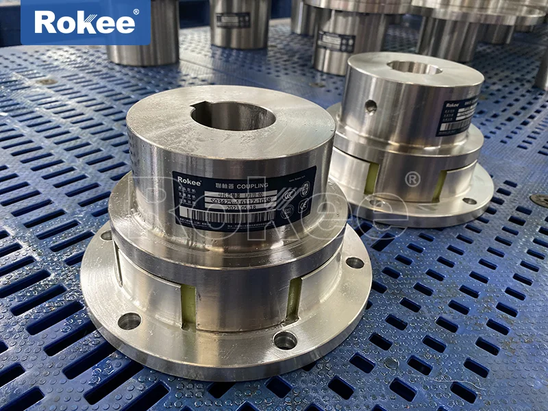
Additionally, there are claw type flexible couplings with flange connections, which include single flange and double flange variants. These couplings are designed to facilitate easy installation and replacement of the elastic element, as they eliminate the need to axially move the semi-couplings when replacing the spider. The single flange variant features a single transition flange, while the double flange variant has two flanges, providing greater flexibility in installation and alignment.
The wide range of types and performance characteristics of claw type flexible couplings makes them suitable for a diverse array of applications across various industries. In the manufacturing industry, they are widely used in conveyor systems, where they connect motors to conveyor belts, transmitting torque while compensating for misalignments caused by the long length of the conveyor and absorbing vibrations generated by the movement of materials. They are also used in mixers and agitators, where their vibration damping capability helps to reduce noise and protect the motor and gearbox from damage caused by the uneven load of the mixing process.
In the automotive industry, claw type flexible couplings are used in auxiliary systems such as water pumps, air compressors, and power steering pumps. These applications require reliable torque transmission with moderate misalignment compensation and vibration damping, which the claw type flexible coupling provides effectively. They are also used in some electric vehicle drive systems, where their compact design and high efficiency make them suitable for connecting the motor to the transmission.
The aerospace industry uses micro claw type flexible couplings in small precision equipment such as aircraft instruments, navigation systems, and auxiliary power units. These applications require compact, lightweight couplings that can transmit small torques with high precision and reliability, and the micro claw type flexible coupling meets these requirements effectively. The high-temperature resistant variants are also used in some aerospace applications where components operate at high temperatures.
In the agricultural industry, claw type flexible couplings are used in farm machinery such as tractors, harvesters, and irrigation pumps. These applications often involve harsh operating conditions, including dust, dirt, and moderate misalignments, and the claw type flexible coupling’s durability, ease of maintenance, and vibration damping capability make it well-suited for these environments. They connect the engine to various auxiliary components, ensuring reliable power transmission even in rough terrain.
The water treatment industry relies on claw type flexible couplings in pumps and blowers, which are essential for water circulation, filtration, and aeration. These applications require couplings that can withstand wet environments, transmit torque efficiently, and absorb vibrations generated by the pumps. The corrosion-resistant variants, made of stainless steel hubs and water-resistant elastic elements, are particularly suitable for these applications.
In the power generation industry, claw type flexible couplings are used in auxiliary systems such as cooling water pumps, fans, and fuel pumps in thermal power plants, hydropower plants, and wind power plants. They provide reliable torque transmission, compensate for misalignments between the motor and the driven equipment, and absorb vibrations, ensuring the stable operation of the auxiliary systems, which are critical for the overall performance of the power plant.
Laboratory and medical equipment also benefit from the use of claw type flexible couplings, particularly the micro variants. These applications, such as centrifuges, analytical instruments, and medical pumps, require precise torque transmission with minimal vibration and noise, and the compact design of micro claw type flexible couplings makes them ideal for these small, precision devices.
When selecting a claw type flexible coupling for a specific application, several factors need to be considered to ensure optimal performance and reliability. The first factor is the torque capacity, which must match the torque requirements of the transmission system. Selecting a coupling with insufficient torque capacity can lead to premature failure, while selecting one with excessive capacity may result in unnecessary cost and size. The second factor is the type and magnitude of shaft misalignment, as different types of couplings offer different compensation capabilities. It is important to select a coupling that can accommodate the expected misalignments in the application. The operating temperature is another critical factor, as the elastic element’s performance is highly dependent on temperature. For high-temperature applications, a high-temperature resistant variant should be selected to ensure the coupling’s durability.
The operating speed is also an important consideration, as high-speed applications require couplings with good balance performance to avoid excessive vibration. The environmental conditions, such as the presence of oil, water, dust, or corrosive substances, should also be taken into account when selecting the material of the hubs and elastic element. For example, in corrosive environments, stainless steel hubs and resistant elastic elements should be used. Finally, the ease of maintenance and replacement of the elastic element should be considered, as this can reduce downtime and maintenance costs over the life of the equipment.
In conclusion, the claw type flexible coupling is a versatile and reliable component in mechanical power transmission systems, offering a unique combination of simplicity, cost-effectiveness, vibration damping, and deviation compensation. Its well-designed structure, consisting of metal hubs and an elastic element, enables it to transmit torque efficiently while protecting the transmission system from the negative impacts of misalignment and vibration. The various types of claw type flexible couplings, each tailored to specific application requirements, make them suitable for a wide range of industries, from manufacturing and automotive to aerospace and agriculture. By understanding the structure, performance characteristics, types, and applications of claw type flexible couplings, engineers and designers can select the most appropriate coupling for their specific needs, ensuring the efficient and reliable operation of mechanical systems. As technology continues to advance, it is likely that new materials and designs will further enhance the performance and versatility of claw type flexible couplings, expanding their applications in even more diverse and demanding environments.