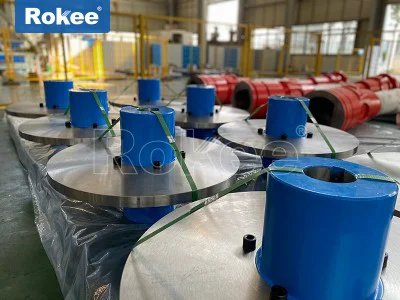
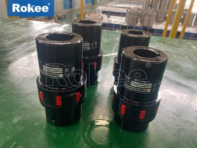
Jaw Flex Couplings
Jaw flex coupling is a mechanical connection device widely used in industrial transmission systems. It achieves power transmission between two shafts through a special claw shaped structure, while allowing for a certain degree of axial, radial, and angular deviation. This type of coupling is named after its unique "claw tooth meshing" design and plays a key role in various mechanical transmission systems.
Compared with traditional rigid couplings, jaw flex couplings have significant advantages: they can effectively compensate for installation errors, absorb vibrations and impacts, and protect connected equipment from excessive loads. At the same time, its compact structure, high torque transmission, and no need for lubrication make it widely used in many industrial fields.
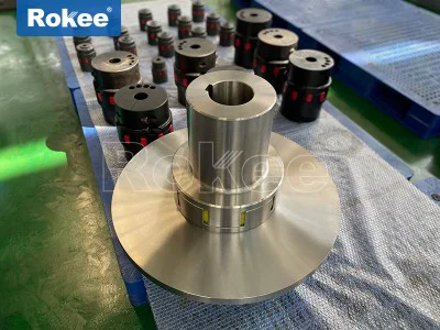
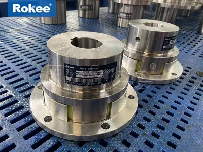
Jaw flex coupling mainly consists of the following parts:
Two half couplings: installed on the drive shaft and driven shaft respectively, usually forged from high-strength alloy steel
Elastic element: located between the two halves of the coupling, common materials include polyurethane, rubber, nylon, etc
Claw tooth structure: Multiple protruding claw teeth machined on the end face of the half coupling, usually distributed uniformly in a radial pattern
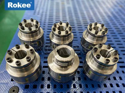
Connecting bolt: used to fix the two halves of the coupling, some designs adopt maintenance free clamping connection method
The jaw flex coupling transmits torque through the meshing of claw teeth on the two halves of the coupling, and the elastic element in the middle allows for deviation in three directions while transmitting power:
Axial deviation compensation: The compression deformation of the elastic element allows for a small amount of axial displacement between the two axes
Radial deviation compensation: The clearance between the claw teeth and the elastic element allows for radial deviation
Angular deviation compensation: The bending deformation of elastic elements allows for small angles of misalignment between the two axes
When torque is transmitted, the claw teeth on the driving side transmit force to the claw teeth on the driven side by squeezing the elastic element. The elastic element absorbs vibration and impact energy during this process, protecting the connected equipment.
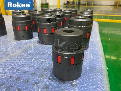
Classified by elastic components
Polyurethane Jaw Coupling:
The elastomer is made of polyurethane material
High elasticity, excellent shock absorption performance
Oil resistant, aging resistant, long service life
The working temperature range is usually between -30 ℃ and+80 ℃Rubber Jaw Coupling:
Using natural or synthetic rubber as elastic components
Excellent damping characteristics and good vibration absorption effect
Low cost, but poor temperature and oil resistance
Suitable for low-speed and high torque applicationsNylon Jaw Coupling:
Using engineering nylon as elastic material
High mechanical strength and good wear resistance
Suitable for high-speed applications
But the elasticity is relatively poor and the compensation ability is limited
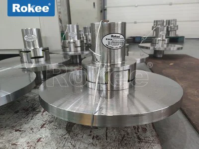
Classified by structural design
Standard Jaw Coupling:
The most common symmetrical design
The number and shape of claws on both sides are the same
No need to distinguish directions during installationAsymmetric Jaw Coupling:
The design of the claws on both sides is different
Can achieve special torque transmission characteristics
Commonly used for transmission systems with special requirementsJaw Coupling with intermediate:
Add intermediate connectors
Allow for greater deviation compensation
Suitable for long-distance axis connections
Key performance parameters
Rated torque: the maximum torque value that the coupling can continuously transmit
Maximum torque: The peak torque that can be sustained in a short period of time, usually 2-3 times the rated torque
Speed range: The maximum allowable working speed, which is related to the size and balance level of the coupling
Deviation compensation capability:
Axial direction: usually 0.5-5mm
Radial: usually 0.2-2mm
Angular direction: usually 0.5 ° -3 °Moment of inertia: affecting the dynamic response characteristics of the system
Working temperature range: depends on the elastic element material
Selection considerations
Load characteristics:
Constant load or variable load
Is there any impact or vibration
Starting frequency and braking requirementsEnvironmental conditions:
ambient temperature
Are there any oil stains, chemicals, or dust present
Humidity situationSpace limitations:
Installation space size
Do you need easy disassembly
Axial movement demandEconomy:
Initial cost
maintenance cost
Expected service life
Correct installation steps
Preparation work:
Check the size matching of the shaft and coupling
Clean the shaft end and coupling inner hole
Prepare suitable installation toolsInstall the half coupling:
Use specialized tools to press the half coupling onto the shaft
Ensure that the specified axial positioning position is achieved
Check radial and axial runoutAlignment correction:
Use a dial gauge or laser centering device for precise centering
Ensure that the deviation is within the allowable range
Pay special attention to the impact of angular deviationFinal fixation:
Tighten the connecting bolts according to the prescribed torque
Check if all fasteners are secure
Manually rotate to check for interference
Key points of daily maintenance
Regular inspection items:
Wear condition of elastic components
Is there any abnormal noise or vibration
Is the connecting bolt loose
Seal integrity (if applicable)Suggested maintenance cycle:
Monthly: Visual inspection of appearance status
Quarterly: Check the alignment and bolt tightening status
Every year: comprehensive dismantling and inspection, replacement of worn partsCommon problem handling:
Abnormal vibration: Check the alignment and replace worn elastic components
Overheating: Check if the load exceeds the standard and lubrication status (if lubrication is required)
Noise: Check the coordination status of each component and eliminate foreign object interference
Main industrial applications
Pump equipment:
Centrifugal pumps, plunger pumps, etc
Compensation for installation deviation between pump and motor
Vibration caused by absorbing fluid pulsationFan system:
Centrifugal fan, axial flow fan
Reduce vibration transmission caused by rotor imbalance
Allow axial displacement caused by thermal expansionCompressor:
Reciprocating and screw compressors
Buffer the impact load of piston movement
Protect the motor from torsional vibrationConveyor machinery:
Belt conveyor, chain conveyor
Difficulty in compensating for the alignment of the long axis system
Adapt to deviations caused by foundation settlement
Jaw flex couplings as key components in the field of mechanical transmission, continue to innovate and develop with the advancement of industrial technology. In the future, higher performance and more intelligent jaw couplings will play a more important role in industry and intelligent manufacturing, providing more reliable and efficient connection solutions for various rotating equipment.
Jaw flex couplings stand as one of the most versatile and widely adopted mechanical power transmission components in modern industrial systems, serving as a critical link between driving and driven shafts that balances rigid torque transfer and flexible misalignment accommodation. Unlike fully rigid couplings that demand perfect shaft alignment and offer no tolerance for operational movement or vibration, jaw flex couplings integrate a unique combination of metallic structural components and elastic damping elements, creating a robust yet adaptable connection that addresses the inherent challenges of real-world machinery operation. At its core, the fundamental design of a jaw flex coupling is defined by simplicity and functional efficiency, consisting of two precision-engineered metallic hubs and a central elastic insert, commonly referred to as a spider, that fits snugly between the interlocking jaws of each hub. This three-part construction eliminates unnecessary complexity, making the coupling easy to install, disassemble, and maintain even in confined industrial spaces, a key advantage that has solidified its place across countless manufacturing, processing, and mechanical systems worldwide. Each metallic hub is machined with a series of evenly spaced, protruding jaws around its outer perimeter, positioned to mesh loosely with the jaws of the opposing hub without direct metal-to-metal contact under normal operating conditions; this gap is precisely filled by the elastic spider, which acts as both a torque transmitter and a shock absorber. The hubs themselves are typically forged or cast from high-strength ferrous or non-ferrous metals, selected based on the specific load, speed, and environmental demands of the application, with material choices ranging from durable cast iron for heavy-duty, high-torque setups to lightweight aluminum alloys for low-load, high-speed systems that require reduced rotational inertia. The jaw profiles are meticulously machined to ensure uniform contact with the elastic spider, distributing torque evenly across the elastic element’s surface to prevent localized stress concentrations that could lead to premature wear or failure, while also maintaining consistent rotational alignment between the two shafts.
The structural integrity of jaw flex couplings is further enhanced by the design of the jaw and spider interface, which operates on a compression-based power transfer mechanism rather than shear stress, a distinction that sets this coupling type apart from many other flexible coupling designs. When torque is applied from the driving shaft, the jaws of the driving hub push against the corresponding lobes of the elastic spider, compressing the elastic material to transfer rotational force to the jaws of the driven hub; this compression mode allows the elastic element to handle higher torque loads with greater structural stability compared to shear-based elastic couplings, where the elastic material is stretched or twisted rather than compressed. This design also creates a failsafe operational feature: in the event that the elastic spider becomes worn, damaged, or completely fractured due to extreme loads or prolonged use, the metallic jaws of the two hubs will make direct contact, allowing the coupling to continue transmitting torque temporarily to avoid catastrophic system failure and unplanned downtime. While this failsafe mode results in increased vibration, noise, and accelerated wear on the hub jaws, it provides a critical window for maintenance teams to replace the elastic spider during scheduled downtime, protecting more valuable and complex components such as motors, gearboxes, and driven equipment from sudden damage. The elastic spider, as the heart of the jaw flex coupling’s performance, is molded from a range of elastomeric materials, each engineered to deliver specific mechanical properties tailored to diverse operating conditions, including hardness, temperature resistance, chemical compatibility, vibration damping, and flexibility. These material variations, combined with subtle design modifications to the hub jaws and spider geometry, give rise to distinct classifications of jaw flex couplings, each optimized for specific operational parameters such as shaft misalignment, rotational speed, torque capacity, and environmental exposure.
Performance characteristics of jaw flex couplings are directly shaped by their structural design and material composition, making them suitable for a broad spectrum of industrial applications that require a balance of power transfer efficiency and operational flexibility. One of the most notable performance traits is their ability to accommodate multiple forms of shaft misalignment, a common issue in industrial machinery caused by manufacturing tolerances, thermal expansion, mechanical vibration, or foundation shifting during operation. Jaw flex couplings can effectively compensate for angular misalignment, parallel misalignment, and axial shaft movement within specified limits, absorbing small positional shifts without transferring excessive stress to the shaft bearings or connected equipment. This misalignment tolerance reduces the need for ultra-precise initial shaft alignment, lowering installation time and costs, while also extending the service life of bearings and seals by minimizing radial and axial loads that lead to premature wear. Beyond misalignment accommodation, these couplings excel at dampening torsional vibration and shock loads, which are prevalent in machinery with intermittent operation, rapid start-stop cycles, or fluctuating torque demands such as pumps, compressors, and conveyor systems. The elastic spider absorbs and dissipates vibrational energy generated during operation, reducing noise levels and preventing resonant vibration that can damage sensitive components or compromise the stability of the entire mechanical system. Unlike lubricated couplings that require regular maintenance to prevent friction and wear, standard jaw flex couplings are lubrication-free under normal operating conditions, as the elastic spider eliminates direct metal contact between the hubs, reducing internal friction and eliminating the need for ongoing lubrication tasks; this low-maintenance design is particularly valuable in remote or hard-to-access industrial settings where routine maintenance is challenging.
Torsional stiffness is another key performance metric that varies across different jaw flex coupling variants, allowing users to select a model that aligns with the precision and flexibility needs of their application. Some variants feature a stiffer elastic spider and compact jaw design, delivering higher torsional stiffness for applications that require consistent rotational positioning and minimal backlash, such as machine tools, automation equipment, and precision conveying systems. Other variants utilize a softer, more flexible elastomer for the spider, prioritizing vibration damping and misalignment tolerance over absolute stiffness, making them ideal for heavy machinery that operates under high shock loads or in unstable mounting conditions. Torque transmission capacity ranges widely across jaw flex coupling sizes and designs, from small-scale units for low-power, high-speed precision equipment to heavy-duty models capable of transferring substantial torque in large industrial machinery such as mining equipment, material processing systems, and power generation units. The torque capacity is closely linked to the size and number of hub jaws, the surface area of the elastic spider in contact with the jaws, and the compressive strength of the elastomer material, with larger couplings featuring more jaws or wider jaw profiles to distribute torque across a larger contact area and handle higher load demands. Additionally, jaw flex couplings exhibit excellent thermal stability within their designed operating temperature ranges, with elastomer materials selected to resist hardening, cracking, or softening when exposed to extreme cold or elevated temperatures, as well as common industrial fluids such as oils, lubricants, and mild chemicals, ensuring consistent performance in harsh operating environments without rapid degradation of the elastic element.
Jaw flex couplings are categorized into several distinct types based on two primary factors: the material and design of the elastic spider, and the structural configuration of the metallic hubs. These classifications are not arbitrary but are engineered to address specific operational challenges, allowing engineers and maintenance teams to select the optimal coupling for each unique application. The most common classification is based on the elastomer material of the spider, with each material offering a unique set of performance attributes. Standard nitrile rubber spiders are the most widely used, offering a balanced combination of flexibility, vibration damping, oil resistance, and cost-effectiveness for general-purpose industrial applications; they perform reliably in moderate temperature ranges and resist degradation from common hydraulic fluids and lubricants, making them suitable for pumps, fans, and general conveyor systems. Polyurethane spiders offer higher torque capacity and greater resistance to abrasion, ozone, and environmental weathering compared to nitrile rubber, with slightly lower vibration damping but enhanced durability in outdoor or exposed industrial settings, as well as applications with moderate to high torque demands. High-performance thermoplastic elastomer spiders are engineered for extreme temperature conditions, withstanding both sub-zero temperatures and elevated heat levels that would cause standard rubber to fail, while also offering excellent chemical resistance to harsh industrial solvents and corrosive substances; these are commonly used in chemical processing, high-temperature manufacturing, and outdoor heavy machinery. For extremely low-speed, high-torque applications, rigid metal-filled or impregnated spiders are utilized, offering minimal flexibility but maximum torque transfer and temperature resistance, though they eliminate most vibration damping capabilities and are reserved for specialized heavy-duty setups.
Beyond spider material, jaw flex couplings are also classified by hub design and spider geometry, each tailored to specific installation constraints and operational needs. Standard solid-center spider couplings are the most prevalent, featuring a fully enclosed central core that provides maximum structural support and stability, ideal for general-purpose applications where the distance between shaft ends is consistent and sufficient. Open-center spider couplings are designed for applications where the gap between driving and driven shafts is minimal, with a hollow central section that allows for closer shaft positioning while maintaining the core elastic damping function; these are commonly used in compact machinery where space is limited, though they have slightly lower rotational speed limits compared to solid-center designs. Split-hub jaw flex couplings feature a two-piece hub design that can be mounted onto shafts without removing connected equipment, simplifying installation and replacement in situations where full disassembly of the machinery is impractical or time-consuming; this design is particularly valuable in large-scale industrial systems where downtime must be minimized. Another specialized variant is the snap-wrap spider coupling, which features a flexible, open-end spider that can be installed or removed radially without disturbing the alignment of the hubs, eliminating the need to reposition shafts or re-calibrate alignment during maintenance; this design streamlines replacement of worn elastic elements, reducing maintenance time and labor costs significantly. Additionally, jaw flex couplings are available in different jaw configurations, including standard straight jaws for general use and curved or contoured jaws for smoother torque transfer and reduced stress on the elastic spider, enhancing durability in high-cycle or high-speed applications.
The versatility of jaw flex couplings, driven by their diverse structural designs and performance characteristics, has led to their widespread adoption across nearly every major industrial sector, with applications spanning light-duty precision equipment to heavy-duty industrial machinery. In the fluid handling industry, jaw flex couplings are extensively used in centrifugal pumps, positive displacement pumps, vacuum pumps, and compressors, where they absorb vibration generated by fluid flow and pressure fluctuations, compensate for minor shaft misalignment caused by pipe stress or thermal expansion, and protect motor and pump bearings from premature wear. Their failsafe design is especially critical in pumping systems, where sudden coupling failure could lead to process disruptions, fluid leakage, or damage to expensive pump components. In material handling and manufacturing operations, these couplings connect drive motors to conveyor belts, elevators, mixers, and agitators, handling the fluctuating torque loads and shock impacts common in bulk material transport and processing; the vibration damping properties reduce noise in busy production facilities and extend the service life of conveyor rollers and drive chains. In the machine tool and automation sector, jaw flex couplings with high torsional stiffness and minimal backlash are used in CNC machine tools, robotic arms, and precision positioning systems, ensuring accurate rotational transfer and consistent positioning for machining, assembly, and packaging operations, while still accommodating small misalignments that occur during prolonged machine operation.
Heavy industrial sectors such as mining, construction, and metal processing rely on heavy-duty jaw flex couplings to connect large motors, gearboxes, and crushing or grinding equipment, where high torque capacity and shock absorption are essential. These couplings withstand the extreme loads and vibration generated by heavy machinery, protecting drivetrain components from damage and reducing the frequency of costly repairs in rugged, high-demand environments. In the power generation and HVAC industries, jaw flex couplings are used in fans, blowers, generators, and small turbine systems, where they balance efficient power transfer with vibration isolation, preventing mechanical noise from spreading and ensuring smooth, consistent operation of ventilation and power equipment. They are also widely employed in agricultural machinery, connecting engines to pumps, conveyors, and processing equipment, where durability and resistance to dust, dirt, and moderate moisture are critical. Even in marine and offshore applications, specialized corrosion-resistant jaw flex couplings with chemical-resistant elastomer spiders are used in onboard pumping and mechanical systems, standing up to saltwater exposure and harsh marine conditions without rapid degradation.
While jaw flex couplings are designed for durability and low maintenance, understanding their operational limits and proper selection criteria is essential to maximizing their service life and ensuring reliable performance. Selecting the wrong coupling variant for an application can lead to premature elastic spider wear, reduced torque capacity, increased vibration, or even complete coupling failure, so careful consideration of torque requirements, rotational speed, shaft misalignment, operating temperature, and environmental conditions is paramount during the design and replacement process. It is important to match the coupling’s torque rating to the actual operating load of the machinery, accounting for peak torque and shock loads rather than just average running torque, to avoid overloading the elastic spider and causing premature failure. Regular visual inspection of the elastic spider for signs of wear, cracking, compression set, or chemical degradation is recommended, as a damaged spider can lead to increased backlash, reduced vibration damping, and eventual metal-to-metal contact between the hub jaws. In applications with frequent start-stop cycles or reversing operation, the elastic spider will experience accelerated wear, so more frequent inspections and replacement may be necessary compared to continuous, unidirectional operation. Additionally, ensuring proper shaft fit and alignment during installation, even with the coupling’s misalignment tolerance, will reduce unnecessary stress on the elastic element and extend the overall service life of the coupling and connected equipment.
In summary, jaw flex couplings represent a perfect synthesis of simplicity, durability, and functional versatility in mechanical power transmission, with their modular three-part structure, diverse material options, and adaptable design making them suitable for an unparalleled range of industrial applications. Their ability to transmit torque reliably, absorb vibration and shock loads, accommodate minor shaft misalignment, and operate in a failsafe mode sets them apart from more complex and specialized coupling types, while their low-maintenance, lubrication-free design reduces operational costs and downtime across industrial systems. As industrial machinery continues to evolve toward higher efficiency, greater reliability, and more compact designs, jaw flex couplings will remain a foundational component in power transmission systems, adapting through material and design advancements to meet the changing demands of modern manufacturing, processing, and mechanical engineering. Their enduring popularity stems not from complex innovation, but from a proven, practical design that consistently delivers consistent performance, durability, and value in even the most demanding industrial environments, solidifying their role as an indispensable component in global industrial operations.