Cardan Drive Shafts
In modern mechanical transmission systems, cardan drive shafts play an indispensable role. As a key link in power transmission, it can stably and reliably transmit torque and rotational motion under complex working conditions where the angle and distance between shafts are constantly changing.
A cardan drive shaft is a mechanical device that can connect two shafts with constantly changing relative positions and transmit power and rotational motion. Its core function is to solve technical problems caused by changes in the angle and distance between axes during power transmission, ensuring reliable power transmission under various complex working conditions. This unique adaptability makes cardan drive shafts an indispensable key component in modern transmission systems.
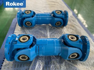
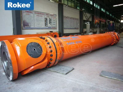
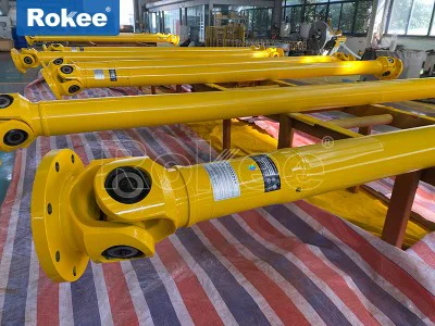
From the perspective of structural composition, a typical cardan drive shaft consists of three main parts: universal joint, drive shaft tube, and intermediate support. The universal joint is the core component for compensating for angle changes. The transmission shaft tube is responsible for transmitting torque, while the intermediate support is used for supporting the long axis system and suppressing vibration. According to different application requirements, cardan drive shafts can be designed in various forms. It can be divided into two categories based on whether it has length adjustment ability: telescopic and non telescopic. The telescopic transmission shaft compensates for changes in axial length through a sliding spline structure, making it particularly suitable for situations where the distance between shafts may change, such as the transmission between a car gearbox and a drive axle; Non telescopic transmission shafts are suitable for situations where the distance between shafts is basically fixed, with a relatively simple structure and better rigidity.
From the perspective of the types of universal joints, cardan drive shafts can be divided into two categories: rigid universal joint drive shafts and flexible universal joint drive shafts. Rigid universal joints rely on hinge type connections of components to transmit power, which are further divided into non-uniform universal joints (such as common cross axis type), quasi constant velocity universal joints (such as double joint type, three pin axis type), and constant velocity universal joints (such as cage type, ball fork type). Flexible universal joints rely on the deformation of elastic elements to transmit power, which has the advantage of buffering and vibration reduction, but their load-bearing capacity is relatively small. Each type has its specific applicable scenarios and performance characteristics, and understanding these differences is crucial for proper selection and design.
In terms of application fields, cardan drive shafts almost cover all mechanical equipment that requires power transmission. In the automotive industry, whether it is front wheel drive, rear wheel drive or four-wheel drive vehicles, the cardan drive shaft is the core component of the transmission system. The transmission shaft of rear wheel drive vehicles connects the gearbox and the drive axle, usually using a cross axis universal joint; The constant velocity cardan drive shaft of front wheel drive vehicles is connected to the differential and drive wheels, often using ball cage constant velocity universal joints. In the industrial field, cardan drive shafts are widely used in various heavy-duty equipment such as machine tools, steel rolling equipment, and mining machinery. The key role of cardan drive shafts is also indispensable in fields such as ship propulsion systems, generator sets, and railway locomotives.
With the advancement of materials science and manufacturing technology, modern cardan drive shafts are developing towards high performance, lightweight, and long lifespan. Innovative achievements such as carbon fiber composite transmission shafts, high-strength alloy steel universal joints, and high-performance sealing technologies continue to emerge, greatly expanding the application boundaries of universal transmission shafts. At the same time, with the development of new energy vehicles and intelligent driving technology, higher requirements have been put forward for the efficiency, quietness, and reliability of universal transmission shafts, which also promotes continuous innovation and evolution of transmission shaft technology.
As a precision power transmission mechanism, the structural design and working principle of the universal transmission shaft reflect clever ideas in mechanical engineering. A deep understanding of these core contents is crucial for the correct selection, use, and maintenance of cardan drive shafts. The typical structure of a transmission shaft consists of three key parts: universal joints, transmission shaft tubes, and intermediate supports, each with its unique functional characteristics and design considerations.
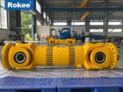
The universal joint is undoubtedly the core of the entire system, which determines the ability of the transmission shaft to adapt to angle changes and transmission efficiency. The cross axis universal joint, as the most traditional type of rigid universal joint, consists of a cross axis, four needle roller bearings, and two universal joint forks. This structure is simple and reliable, but it has inherent non-uniformity - when the input shaft rotates at a constant speed, the instantaneous angular velocity of the output shaft will fluctuate periodically. To solve this problem, double universal joint arrangement is usually adopted in engineering practice, and constant speed transmission is achieved through specific spatial geometric relationships (i.e. maintaining equal angles between the two universal joints and keeping the universal joint forks at both ends of the intermediate shaft in the same plane). In contrast, the cage type constant velocity universal joint can achieve true equal angular velocity transmission through precise raceway design and steel ball arrangement, making it particularly suitable for high demand applications such as steering drive axles. This universal joint consists of an outer planet wheel, an inner planet wheel, steel balls, and a cage (ball cage). The six steel balls roll in a precision machined track and always remain on the bisector of the angle between the two axes, ensuring synchronous rotation of the input and output shafts.
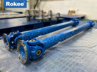
As the main body of torque transmission, the design of the transmission shaft tube is also full of technical content. Modern transmission shaft tubes often adopt hollow structures, which not only ensure torsional strength but also achieve lightweight design and increase critical speed. The critical speed of the transmission shaft refers to the speed at which resonance occurs when the working speed of the shaft is consistent with its natural frequency. Exceeding this speed may cause the transmission shaft to break. By adopting a hollow tube structure, the stiffness of the shaft can be increased while reducing weight, thereby pushing the critical speed above the working speed. For transmission shafts with longer lengths, it is usually necessary to design them in sections and add intermediate supports to avoid vibration problems caused by excessively long shaft systems. The two ends of the transmission shaft are usually welded with spline shafts or universal joint forks. The spline connection allows the length of the shaft to be adjusted within a certain range to compensate for changes in the distance between the transmission and the drive axle during vehicle operation.
The intermediate support plays an important role in the long axis system, as it not only reduces shaft deflection but also effectively suppresses vibration. A typical intermediate support consists of bearings, rubber buffers, and brackets, and the stiffness and damping characteristics of the rubber components directly affect the vibration reduction effect of the support. A well-designed intermediate support can absorb the vibration energy of the transmission shaft, preventing it from being transmitted to the vehicle body or frame, thereby improving ride comfort and equipment stability. In heavy vehicles and industrial equipment, the design of intermediate supports is particularly critical as it needs to withstand larger loads and more demanding working environments.
The working principle of universal transmission shaft demonstrates the exquisite mechanical adaptability. When there is an angular deviation between two connected shafts, the cross shaft or steel ball inside the universal joint compensates for this deviation through its own rotation and swing, allowing power to be continuously transmitted. Taking the cross axis universal joint as an example, when the driving shaft rotates, the cross axis rotates simultaneously with respect to the two universal joint forks. This composite motion allows the driven shaft to obtain rotational power even though there is an angular deviation from the driving shaft.
In the realm of mechanical power transmission, the Cardan drive shaft stands as one of the most versatile and indispensable components, engineered to transfer torque and rotational motion between two shafts that are not collinear, with varying degrees of angular, axial, and radial misalignment. Unlike rigid shaft couplings that demand perfect alignment between driving and driven components, Cardan drive shafts accommodate dynamic shifts in shaft positioning, making them a cornerstone of nearly every industrial and mobile mechanical system that relies on flexible power delivery. This component’s design balances simplicity, durability, and functional adaptability, with structural nuances that directly shape its performance capabilities, classification criteria, and real-world utility across diverse operating environments.
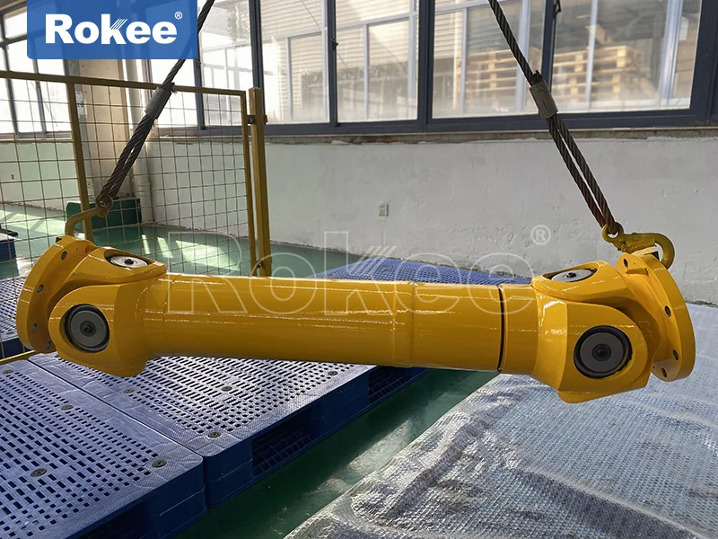
At its core, the standard Cardan drive shaft features a modular, articulated structure optimized for misalignment compensation and torque transmission, with no overly complex moving parts that compromise reliability. The primary building blocks of a conventional Cardan drive shaft include universal joint assemblies, a central shaft tube or telescopic shaft section, and connection interfaces that link the assembly to adjacent drivetrain components. The universal joint, often referred to as a U-joint, is the heart of the system; the most prevalent variant is the cross-type universal joint, which consists of a rigid cross-shaped spindle, four bearing caps, and needle roller bearings housed within each end of the cross. This cross assembly fits snugly into two yoke-shaped connectors—one attached to the driving shaft and the other to the driven shaft—creating a pivoting mechanism that permits angular deflection in two perpendicular planes. For enhanced flexibility, many Cardan drive shafts incorporate a telescopic splined section between the two universal joints, which enables axial adjustment to accommodate changes in distance between connected shafts during operation, such as suspension travel in mobile equipment or thermal expansion in fixed industrial machinery. The central shaft tube is typically hollow, crafted from high-strength alloy steel to minimize rotational inertia while maximizing torsional rigidity, reducing energy loss and preventing bending under heavy loads. Solid shaft variants exist for ultra-heavy-duty applications where extreme torque resistance is non-negotiable, though they are less common due to higher weight and inertia. Every structural element is precision-engineered to work in tandem: the bearings reduce friction between moving parts to extend service life, the yokes distribute stress evenly across the joint to avoid premature failure, and the telescopic design ensures continuous power transfer even as shaft alignment shifts dynamically.
The performance of a Cardan drive shaft is defined by a set of interconnected mechanical properties that dictate its suitability for specific operating conditions, with no reliance on external certifications or branded enhancements to deliver consistent functionality. Foremost among these is torque transmission capacity, which refers to the maximum rotational force the shaft can handle without deformation, fracture, or performance degradation. This capacity is directly tied to material strength, cross-sectional dimensions of the shaft and universal joint components, and heat treatment processes that boost hardness and fatigue resistance. Angular misalignment tolerance is another pivotal performance metric; standard cross-type Cardan shafts typically accommodate deflection angles ranging from a few degrees up to 45 degrees, depending on the design, with larger angles possible in specialized variants though often accompanied by minor speed fluctuations. Axial displacement capability, enabled by the telescopic spline section, allows the shaft to lengthen or shorten by a predefined range, adapting to installation tolerances and operational movement without imposing excessive stress on connected components. Transmission efficiency is equally critical, as friction within the universal joints and shaft assembly can lead to power loss; high-quality Cardan drive shafts minimize this loss through precision machining of bearing surfaces, smooth spline profiles, and proper lubrication retention, achieving efficiency rates that support energy conservation in both low-speed, high-torque and high-speed, low-torque applications. Durability and fatigue resistance round out core performance traits, as these shafts often operate in harsh conditions—exposure to vibration, temperature extremes, dust, moisture, and cyclic loading. Robust structural design, corrosion-resistant coatings, and sealed bearing assemblies enhance longevity, ensuring reliable performance over extended service intervals without frequent maintenance. Additionally, dynamic balance is a key performance consideration, especially for high-speed applications; a well-balanced Cardan drive shaft reduces vibration, noise, and wear on adjacent bearings and drivetrain parts, preserving overall system stability and preventing premature component failure.
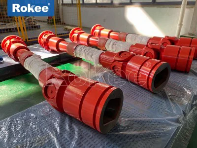
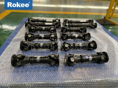
Cardan drive shafts are categorized into distinct types based on structural design, load-bearing capacity, operational speed, and intended use cases, with each variant tailored to address specific transmission challenges. The most fundamental classification is based on universal joint configuration, encompassing single Cardan shafts, double Cardan shafts, and constant velocity (CV) Cardan shafts. Single Cardan shafts, the simplest and most widely used type, feature one universal joint at each end connected by a fixed or telescopic shaft; they excel in moderate misalignment scenarios and are cost-effective for general-purpose applications, though they exhibit minor speed fluctuations at larger deflection angles. Double Cardan shafts address this limitation by integrating two pairs of cross-type universal joints linked by an intermediate short shaft, effectively canceling out velocity variations and enabling smooth power transfer even at near-maximum angular deflection. This design is ideal for applications requiring consistent rotational speed alongside high misalignment tolerance, such as heavy-duty mobile machinery and long-distance industrial transmission lines. Constant velocity Cardan shafts, often referred to as CV joint drive shafts, utilize a ball-and-cage or tripod joint design instead of a cross spindle, maintaining a constant output speed regardless of deflection angle. These shafts are engineered for high-speed, precision-critical applications where speed consistency and minimal vibration are paramount, though they typically have lower torque capacity than cross-type variants. Beyond joint configuration, Cardan drive shafts are classified by load capacity into light-duty, medium-duty, heavy-duty, and ultra-heavy-duty models. Light-duty Cardan shafts feature compact dimensions, low inertia, and moderate torque capacity, designed for small-scale industrial equipment, light automotive systems, and precision machinery where space is limited and loads are minimal. Medium-duty shafts strike a balance between torque capacity and operational flexibility, suitable for a wide range of general industrial machinery, agricultural equipment, and medium-sized commercial vehicles. Heavy-duty Cardan shafts are constructed with thicker, high-strength materials, reinforced universal joints, and oversized bearings to handle extreme torque loads and harsh operating conditions, commonly deployed in heavy construction machinery, mining equipment, and large industrial processing systems. Ultra-heavy-duty variants represent the pinnacle of load-bearing design, with solid shaft construction, heavily reinforced joints, and specialized heat treatment, built to withstand the most demanding heavy-industry applications such as steel rolling mills, large marine propulsion systems, and heavy conveyor systems. Additional niche types include telescopic long Cardan shafts for extended transmission distances, ultra-short Cardan shafts for extremely confined installation spaces, and hollow penetration Cardan shafts for specialized industrial processes requiring unique mounting configurations.
The adaptability of Cardan drive shafts, rooted in their structural versatility and performance diversity, has led to their integration across an extensive array of industries and mechanical systems, powering everything from mobile transportation to fixed industrial manufacturing. In the automotive and transportation sector, Cardan drive shafts are ubiquitous, serving as the critical link between the transmission and drive axle in rear-wheel-drive, four-wheel-drive, and all-wheel-drive vehicles. They accommodate the vertical movement of suspension components during travel, ensuring uninterrupted power delivery to the wheels even as the vehicle navigates uneven terrain. Light-duty passenger vehicles rely on compact, balanced Cardan shafts for smooth, quiet operation, while heavy commercial trucks, buses, and off-road vehicles utilize heavy-duty variants to handle the high torque generated by large engines and the rigors of heavy hauling. Agricultural machinery represents another major application area, where Cardan drive shafts power tractors, combine harvesters, plows, and other farm equipment. These shafts transmit power from the tractor’s power take-off (PTO) to attached implements, adapting to the uneven ground conditions common in farming operations and accommodating the angular shifts of articulated farm machinery. Their ability to handle high torque at low speeds makes them perfectly suited for the heavy, repetitive workloads of agricultural production, supporting tasks ranging from planting and harvesting to material handling.
In the construction and mining industries, Cardan drive shafts are integral to the functionality of heavy machinery such as excavators, bulldozers, cranes, loaders, and drilling rigs. These machines operate in extremely harsh environments with heavy loads, constant vibration, and significant shaft misalignment, and heavy-duty Cardan shafts deliver the reliable torque transmission needed to power hydraulic systems, track drives, and lifting mechanisms. The shafts’ ability to withstand shock loads and extreme angular deflection ensures that construction and mining equipment can operate efficiently in rugged, off-site locations without drivetrain failure. Industrial manufacturing and processing facilities rely on Cardan drive shafts across a multitude of applications, including metalworking machinery, textile equipment, food processing lines, pumping systems, and conveyor belts. In steel mills, for example, ultra-heavy-duty Cardan shafts transfer power to rolling mills and straightening machines, enduring extreme torque and thermal stress while compensating for shaft movement during metal forming processes. In general manufacturing, medium and light-duty Cardan shafts power assembly lines, machine tools, and material handling equipment, offering flexible, low-maintenance power transmission that adapts to the precise alignment needs of automated production systems. The ability to accommodate installation errors and operational shaft movement reduces downtime and simplifies equipment setup, making them a staple in industrial drivetrain design.
Beyond these core sectors, Cardan drive shafts find specialized use in marine, aerospace, and renewable energy systems, showcasing their unparalleled versatility. In marine applications, they connect propulsion engines to propeller shafts in boats and ships, accommodating the slight movement of the engine and propeller shaft due to wave action and vessel movement, ensuring efficient power transfer in both small watercraft and large commercial vessels. In aerospace, lightweight, precision-engineered Cardan shafts are used in aircraft and helicopter systems to transmit power to control surfaces, rotors, and auxiliary components, where low weight, high reliability, and precise motion transfer are critical. For renewable energy, particularly wind turbine systems, Cardan drive shafts link turbine blades to generator systems, compensating for shaft misalignment caused by wind turbulence and structural movement, enabling consistent power generation even under variable wind conditions. This cross-industry utility stems from the Cardan drive shaft’s core design principle: delivering reliable, flexible power transmission without compromising on durability or efficiency, regardless of the operating environment or load demands.
As mechanical engineering continues to evolve toward more efficient, compact, and durable drivetrain systems, the Cardan drive shaft remains a vital component, with ongoing design refinements focused on enhancing performance metrics such as torque capacity, misalignment tolerance, and service life. Advances in material science, including the use of high-strength lightweight alloys and advanced heat treatment processes, have further expanded the capabilities of Cardan drive shafts, allowing them to meet the demands of modern, high-performance machinery while maintaining their inherent simplicity. What makes the Cardan drive shaft truly irreplaceable is its ability to solve a universal mechanical challenge—transmitting power between misaligned shafts—with a design that is both effective and adaptable. Whether in a small passenger vehicle, a massive industrial mill, a rugged agricultural tractor, or a cutting-edge renewable energy system, the Cardan drive shaft operates silently and reliably, underscoring its status as a foundational element of global mechanical infrastructure. Its structural integrity, diverse performance profiles, and wide-ranging applications solidify its role as a timeless innovation in power transmission, continuing to support the functionality of nearly every sector of modern industry and transportation.