Universal Shaft Joints
Universal shaft joint is an indispensable key component in mechanical transmission systems. It can achieve variable angle power transmission, allowing two shafts that are not on the same axis to be effectively connected and transmit torque and motion. Universal shaft joint is widely used in fields such as automobiles, industrial machinery, aerospace, etc. Its performance directly affects the efficiency and reliability of the transmission system.
The core function of a universal shaft joint is to allow a certain angle between the two connected shafts, while transmitting rotational motion and torque. This characteristic makes it an ideal choice for solving the problem of axis misalignment.
Main structural types
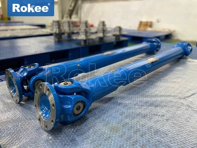
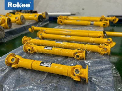
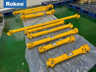
Cross axis universal shaft joint:
The most common type consists of two universal shaft joint forks and a cross shaft
The allowable angle between the two axes is usually between 5 ° and 45 °
Simple structure, strong load-bearing capacity, and easy maintenance
Widely used in fields such as automotive transmission systems and industrial machineryBall cage universal shaft joint:
Composed of star shaped sleeve, spherical shell, steel ball, and retainer
Can achieve constant speed transmission and run more smoothly
Commonly used for the wheel end of front wheel drive vehiclesBall fork universal shaft joint:
The structure is relatively simple, consisting of a ball fork with a raceway and steel balls
Suitable for light load and small angle transmission scenariosScalable universal shaft joint:
Add expansion function on the basis of standard universal shaft joint
Compensatable axial displacement of 0-1000mm
Especially suitable for situations where installation distance may vary
Key performance parameters
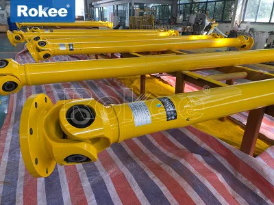
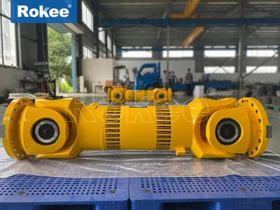
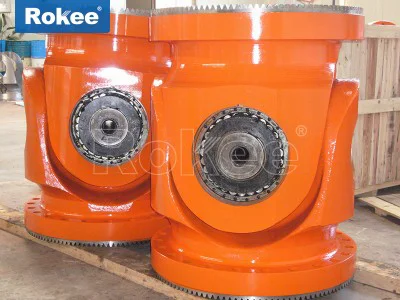
Torque capacity: ranging from a few Newton meters to several thousand Newton meters, heavy-duty joints can even reach up to 900000 Nm
Speed range: Depending on the type, it can reach up to several thousand revolutions per minute
Allowable deflection angle: Single section models typically have a maximum of 37 °, while special designs can reach up to 45 °
Axial compensation capability: The expandable type can provide axial displacement compensation of 0-1000mm
Materials: commonly used 45 # steel, 42CrMo alloy steel, stainless steel, etc., choose according to the working conditions
Special design variants
universal shaft joint with spring type leveling machine:
Using 42CrMo alloy steel material
Installing springs to achieve automatic expansion and contraction
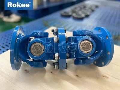
Specially designed for leveling machines, cross cutting machines, slitting machines and other equipmentFluid universal shaft joint:
Used to connect water supply pipelines with water mist nozzles
Can lock the spray angle in any direction
The working pressure can reach 1.2MPa, and it is made of stainless steel or copper alloy materialPrecision universal shaft joint:
The shaft diameter can be as small as 8mm, with a tolerance controlled within 0.005mm
Used in high-precision applications such as aviation and precision instruments
Application fields of universal shaft joint
automotive industry
Rear wheel drive vehicles: installed between the transmission output shaft and the drive axle main reducer input shaft
Front wheel drive vehicles: installed between the front axle half shaft responsible for both driving and steering and the wheels
Steering system: Connect the steering shaft and steering gearindustrial machinery
Machine tool: used for connecting spindle and drive motor
Metallurgical equipment: Heavy equipment such as continuous rolling mills and straightening machines
Mining machinery: conveyors, crushers, etc
Paper Machinery: Drying Cylinder Transmission System
Textile Machinery: Connections between Transmission ShaftsSpecial applications
Aerospace: Aircraft control systems, engine accessory transmissions
Ship: Connection of propulsion shaft system
Robots: Power Transmission at Joints
The manufacturing of precision universal shaft joints involves multiple high-precision machining techniques:
Material selection
Common application: 45 steel, 40Cr
Heavy duty occasion: 42CrMo alloy steel
Corrosion environment: 304/316 stainless steel
Special requirements: Copper alloy, titanium alloy, etc
processing flow
Forging: Obtain preliminary shape and eliminate material defects
Heat treatment: quenching and tempering treatment improves strength and toughness
Precision machining:
Turning: machining cylindrical surfaces such as shaft necks
Milling: Processing complex shapes such as fork heads
Grinding: Ensure high precision of key parts
Assembly: Bearing installation, lubrication system assembly
Balance Test: High speed applications require dynamic balancing
Modern car milling composite processing technology can significantly improve the processing efficiency and quality of universal shaft joints:
Complete multiple processing steps in one clamping operation
The processing time has been reduced from over ten hours using traditional methods to less than 45 minutes
Higher dimensional accuracy and easier assurance of positional tolerances
Selection considerations
Torque demand: Calculate the required torque based on the transmitted power and speed
Speed range: Different structural types have different applicable speeds
Axis deflection angle: Ensure that the selected type meets the actual deflection angle requirements
Installation space: Consider the radial and axial dimensions of the joint
Environmental conditions: Temperature, corrosiveness, dust and other environmental factors affecting material selection
Maintenance requirements: Is regular lubrication necessary and what is the sealing performance
Installation key points
Centering adjustment:
Although universal shaft joints allow for some deviation, good alignment can extend their lifespan
When using a dual universal shaft joint arrangement, the fork heads at both ends of the intermediate shaft should be in the same plane
Use tools such as a dial gauge to detect radial and axial deviationsBolt tightening:
Tighten evenly step by step according to the specified torque value
Use anti loosening measures to prevent looseningLubrication preparation:
Add specified lubricating grease to friction parts such as bearings before assembly
Check if the lubrication channel is unobstructed
routine maintenance
Regular lubrication:
Regularly replenish lubricating grease according to the instructions
Lubrication intervals should be shortened in high temperature and dusty environmentsStatus monitoring:
Regularly check for abnormal vibrations and noise
Monitor whether the working temperature is normal
Check if the seals are intact to prevent grease leakageWear and tear inspection:
Regularly inspect the wear of vulnerable parts such as cross shafts and bearings
Pay attention to changes in the clearance between universal shaft joints
Typical Failure Modes
Cross axis and bearing wear:
Performance: Increased gap, abnormal noise
Reason: Poor lubrication, overload, poor alignment
Solution: Replace worn parts and improve lubricationuniversal shaft joint fork fracture:
Performance: Sudden loss of transmission
Reason: Material defects, fatigue, impact loads
Solution: Replace and analyze the cause of the fractureAbnormal vibration:
Performance: Strong vibration at a specific speed
Reason: Balance disruption, component wear
Solution: Rebalance or replace components
Measures to extend lifespan
Ensure correct installation alignment
Use appropriate lubricants and regularly replenish them
Avoid overloading operation
Regularly check the fastening status
Add protective measures in harsh environments
As a core component in the field of mechanical transmission, the development of universal shaft joint technology directly affects the performance and reliability of various equipment. From simple cross axis structures to precise cage designs, from heavy-duty industrial applications to micro model use, universal shaft joints are constantly adapting to new demands. Proper selection, installation, and maintenance of universal shaft joint joints are crucial for ensuring efficient and stable operation of the transmission system. With the advancement of materials science and manufacturing technology, future universal shaft joint will achieve greater breakthroughs in performance, lifespan, and intelligence.
A universal shaft joint, commonly referred to as a universal joint or U-joint, is a fundamental mechanical coupling component that plays an irreplaceable role in power transmission systems across countless industrial and mechanical fields. It is engineered to connect two rotating shafts with non-collinear axes, enabling the efficient transfer of torque and rotational motion while accommodating angular misalignments between the shafts. Unlike rigid couplings that demand perfect shaft alignment, universal shaft joints offer exceptional flexibility, making them indispensable in systems where shaft displacement, vibration, or spatial constraints prevent precise coaxial alignment.
At its core, the structural design of a standard universal shaft joint is both compact and robust, optimized for balanced load distribution and smooth rotational transmission. The most prevalent structural form consists of two yoke-shaped end fittings, a central cross-shaped spider (also known as a cross shaft), and a set of rolling bearing assemblies integrated into each arm of the cross. The two yokes are mounted on the driving and driven shafts respectively, positioned at a 90-degree angle to each other relative to the central spider, forming a hinged connection that allows pivotal movement in multiple planes. The rolling bearings, typically needle bearings or roller bearings, are fitted between the cross arms and the inner bores of the yokes, serving to minimize friction during rotation, reduce wear on contact surfaces, and enhance the joint’s ability to withstand radial and axial loads. This basic structure ensures that even when the connected shafts form a fixed or variable angle, the joint can maintain continuous, stable power transmission without interrupting the rotational flow.
Beyond the conventional cross-yoke structure, some specialized universal shaft joints feature modified designs to adapt to extreme operating conditions. For instance, certain high-load variants incorporate reinforced bearing seats and thickened cross arms to boost load-bearing capacity, while precision-focused models adopt tighter machining tolerances and sealed bearing structures to prevent the ingress of dust, moisture, or contaminants, thereby extending service life and reducing maintenance demands. The choice of materials further shapes the joint’s structural integrity; high-quality alloy steel is the most common material for critical components like the cross and yokes, thanks to its outstanding tensile strength, fatigue resistance, and wear durability after heat treatment processes such as quenching and tempering. In corrosive environments, stainless steel or brass components are utilized to resist oxidation and chemical erosion, while lightweight aluminum alloys are preferred in applications where weight reduction is a priority, such as aerospace and precision automation equipment, without compromising basic mechanical strength.
The performance attributes of universal shaft joints are the key determinants of their suitability for specific operational scenarios, encompassing angular compensation capacity, torque transmission efficiency, load-bearing limits, rotational stability, and durability. Foremost among these is angular compensation ability, which defines the maximum angle between the driving and driven shafts that the joint can accommodate while maintaining normal operation. Standard universal shaft joints typically handle angular misalignments ranging from 5 degrees to 45 degrees, with general-purpose models performing optimally at angles between 15 and 25 degrees; specialized high-angle designs can exceed this range, catering to applications with extreme shaft offset. This flexibility allows the joint to adapt to dynamic changes in shaft position, such as the vertical movement of vehicle suspension systems or the mechanical vibration of heavy industrial machinery.
Torque transmission efficiency is another core performance metric, directly impacting the overall energy utilization of the power transmission system. A well-designed universal shaft joint minimizes power loss caused by friction and mechanical backlash, achieving efficiency levels of over 95% under moderate operating angles. At smaller misalignment angles, the torque transfer is nearly seamless, with minimal fluctuation in rotational speed; as the operating angle increases, minor speed variations may occur due to the inherent mechanical characteristics of the joint, but this can be mitigated through optimized structural design and paired component configuration. Load-bearing performance is equally critical, with universal shaft joints engineered to withstand not only continuous static torque but also intermittent shock loads and impact forces common in heavy-duty operations. The bearing selection and material strength directly dictate the maximum torque and radial load the joint can handle, with heavy-duty models capable of supporting extremely high loads for large-scale mechanical equipment, while compact variants deliver reliable performance for light-duty, precision-driven systems.
Rotational stability and service life round out the key performance parameters. High-quality universal shaft joints feature balanced structural design and precision machining, reducing rotational vibration and noise even at high operating speeds, which protects adjacent components from excessive wear and extends the overall lifespan of the transmission system. Sealed universal shaft joints, in particular, prevent lubricant leakage and external contamination, maintaining consistent internal lubrication and reducing friction-related degradation, making them ideal for harsh working environments such as construction sites, agricultural fields, and marine settings. Additionally, the fatigue resistance of the joint under prolonged, repetitive operation is a vital performance consideration, as it ensures long-term reliability without premature failure under continuous stress.
Universal shaft joints are categorized into distinct types based on structural design, operational principles, and functional characteristics, each tailored to address specific mechanical requirements and operating conditions. The most widely used classification is based on structural configuration, encompassing single universal joints, double universal joints, constant velocity universal joints, and specialized heavy-duty universal joints, each with unique structural traits and performance advantages.
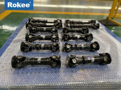
Single universal joints, the simplest and most cost-effective variant, consist of a single cross-yoke assembly as described earlier. They excel in light to medium-duty applications with moderate angular misalignments and low to moderate rotational speeds, offering easy installation, minimal maintenance, and reliable basic power transmission. However, their inherent design leads to slight rotational speed fluctuations at larger operating angles, making them less suitable for high-speed or precision-critical systems that demand uniform rotational output. Double universal joints, constructed by integrating two single universal joints with an intermediate shaft, address the speed fluctuation limitation of single joints. By properly phasing the two joint assemblies, they effectively cancel out rotational unevenness, enabling smoother power transmission at larger angles and over longer shaft distances. This design enhances angular compensation capacity and improves stability, making it ideal for medium to heavy-duty applications with significant shaft offset or extended transmission paths.
Constant velocity (CV) universal joints represent a premium category engineered to maintain consistent rotational speed between driving and driven shafts regardless of the operating angle, eliminating speed fluctuations entirely. Built with advanced structural designs—such as ball-type, cage-type, or tripod-type configurations—these joints distribute load evenly across multiple contact points, ensuring synchronized rotation and smooth torque transfer even at high angles and high speeds. While more complex and structurally intricate than standard cross-yoke joints, CV universal joints deliver unparalleled precision and stability, making them essential for high-performance mechanical systems. Specialized heavy-duty universal joints, meanwhile, feature reinforced structures, oversized bearings, and high-strength materials to handle extreme torque loads and harsh operating conditions, catering to large-scale industrial machinery and heavy equipment that operates under continuous stress and heavy impact.
Further categorization can be based on lubrication and sealing modes, distinguishing between lubricated universal joints and maintenance-free sealed universal joints. Lubricated models are equipped with grease fittings for periodic lubrication, suitable for accessible, high-load environments where routine maintenance is feasible. Sealed, maintenance-free joints come pre-lubricated and hermetically sealed, eliminating the need for regular upkeep and perfect for hard-to-reach installations, cleanroom environments, or harsh settings where contamination risk is high. Additionally, universal shaft joints can be classified by size and application scope, ranging from miniature precision joints for medical devices and electronic equipment to large, heavy-duty joints for industrial manufacturing and construction machinery, covering an extensive spectrum of load and size requirements.
The versatility of universal shaft joints is reflected in their extensive applications across nearly every sector of mechanical engineering, from everyday transportation to cutting-edge industrial automation, agricultural machinery, aerospace systems, marine equipment, and precision manufacturing. In the automotive industry, they serve as core components of drive train systems, connecting transmission output shafts to drive axle input shafts in rear-wheel and four-wheel drive vehicles, accommodating the angular changes caused by suspension movement during travel and ensuring stable power delivery to the wheels. For front-wheel drive vehicles, constant velocity universal joints are integrated into drive axles, enabling smooth torque transmission even during steering maneuvers, balancing both driving and steering functions seamlessly.
In agricultural machinery, universal shaft joints are integral to power take-off (PTO) systems, linking tractors to attached implements such as plows, mowers, balers, and seeders. They adapt to the uneven terrain of farmland, maintaining consistent power transmission as equipment shifts and vibrates during field operations, withstanding high torque loads and frequent start-stop cycles typical of agricultural work. Construction and engineering machinery, including excavators, loaders, cranes, and concrete mixers, rely heavily on heavy-duty universal shaft joints to transfer power between engines and hydraulic pumps or working components, enduring extreme loads, dust, and vibration on job sites while sustaining reliable performance under harsh conditions.
Industrial manufacturing and automation systems leverage universal shaft joints for diverse applications, including conveyor systems, rolling mills, printing presses, textile machinery, and robotic arms. In conveyor setups, they connect drive motors to rollers across non-linear paths, accommodating minor shaft misalignments and ensuring smooth material handling; in robotic systems, they enable multi-axis articulation, supporting precise, flexible movement for automated assembly and manipulation tasks. The precision and compactness of specialized universal joints also make them suitable for precision instruments, medical devices, and aerospace equipment, where lightweight design, high accuracy, and reliable performance under extreme conditions—such as high altitudes and variable temperatures—are non-negotiable.
Marine engineering is another key application area, where universal shaft joints are used in propulsion and steering systems. Constructed from corrosion-resistant materials, they withstand saltwater exposure and hull flexing, transmitting engine power to propeller shafts and connecting steering controls to rudder mechanisms, ensuring stable operation in challenging marine environments. They also find use in wind power generation systems, connecting wind turbine blades to gearbox input shafts, compensating for shaft misalignment caused by wind fluctuations and vibration, and supporting efficient power conversion from wind energy to electrical energy.
In summary, the universal shaft joint stands as a cornerstone of modern mechanical power transmission, blending simple, efficient structural design with exceptional functional versatility. Its ability to accommodate angular misalignment, transmit torque reliably, and adapt to diverse operating conditions has solidified its role across countless industries, supporting the stable operation of machinery ranging from everyday vehicles to large-scale industrial equipment and high-precision automation systems. As mechanical engineering technology continues to advance, the design and manufacturing of universal shaft joints will evolve further, with enhanced performance characteristics—such as higher load capacity, extended service life, and greater precision—expanding their application potential and reinforcing their status as an indispensable mechanical component. Understanding the structure, performance, types, and applications of universal shaft joints is crucial for optimal component selection, system design, and operational maintenance, ensuring efficient, reliable, and long-lasting performance of power transmission systems across all mechanical disciplines.