Curved Tooth Couplings
As a key component in the modern industrial transmission field, the curved tooth coupling has become an indispensable connecting device in heavy machinery and precision equipment due to its unique structural design and excellent performance. This type of rigid flexible coupling, through innovative drum shaped tooth surface design, not only achieves efficient transmission of large torque, but also effectively compensates for installation deviations in axial, radial, and angular directions, solving many limitations of traditional spur gear couplings in complex working conditions.
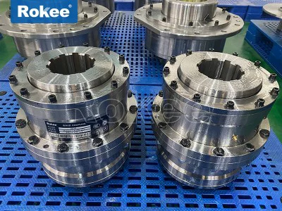
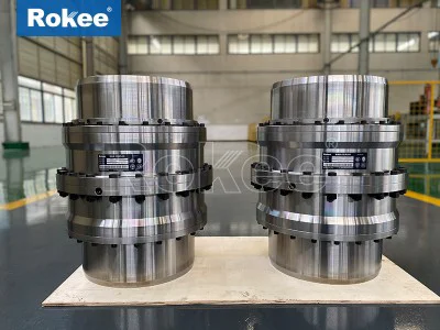
Curved tooth coupling is a precision transmission component composed of an inner gear ring and a flange half coupling with outer teeth. Its core technical feature lies in the special geometric shape of the outer gear. Compared with traditional spur gear couplings, the external teeth of drum gear couplings are not simply straight teeth, but adopt innovative spherical design - the external teeth are made into a spherical profile centered on the gear axis, while increasing the tooth flank clearance. This structural innovation has brought significant performance improvements.
The geometric characteristics of drum shaped teeth are manifested by the fact that both the tooth tip and tooth surface are arc-shaped, forming a double joint structure throughout the coupling, which endows the device with excellent flexibility compensation capability. When the tooth tip of the external gear shaft sleeve is machined into a circular arc shape, the tooth profile presents a distinct drum shaped feature in the cross-section of the tooth center plane and tangent to the pitch cylindrical surface. This drum shaped tooth surface is formed by gradually shifting and superimposing different end sections, and the dotted line formed by the displacement and axial coordinates is called the drum curve, which is a key geometric parameter of the curved tooth coupling. The bulge curve is mostly a segment of arc (some designs also use three segments of arc), and the choice of bulge radius directly affects the compensation ability of the coupling and the distribution of tooth contact stress.
In terms of working mechanism, the curved tooth coupling achieves functional advantages through a unique tooth surface contact method. When there is relative displacement between the two axes, the drum shaped tooth surface significantly improves the contact conditions between the inner and outer teeth: under angular displacement conditions, it avoids the common tooth end edge squeezing phenomenon in straight tooth couplings and eliminates stress concentration points; Simultaneously optimized the friction state of the tooth surface, making the load distribution more uniform. This design enables the coupling to adaptively compensate for a certain range of axis deviations while transmitting torque, including axial displacement (deviation along the axis direction), radial displacement (two axis centerlines parallel but not overlapping), and angular displacement (two axis centerlines forming a pinch angle).
From the perspective of materials science and manufacturing technology, high-quality curved tooth couplings are usually made of high-quality alloy steels such as 42CrMo, 20CrMnTi, etc. After precision carburizing and quenching processes, the tooth surface hardness reaches HRC58-62, ensuring high wear resistance and long-term service life.
In terms of load-bearing capacity and transmission efficiency, the curved tooth coupling performs particularly well. Under the same outer diameter of the inner gear sleeve and maximum outer diameter of the coupling, its load-bearing capacity is on average 15% to 20% higher than that of a spur gear coupling. This is mainly due to the optimized contact stress distribution of the drum shaped tooth surface, which avoids stress concentration caused by edge contact.
The displacement compensation capability is another major advantage of drum gear couplings. When the radial displacement is zero, the allowable angular displacement of a spur gear coupling is usually only 1 °, while a drum gear coupling can reach 1 ° 30 ', increasing the compensation capacity by 50%. This enhanced angular compensation capability enables it to better adapt to shaft installation errors and dynamic deformations during operation. In practical applications, the maximum allowable inclination angle of the curved tooth coupling can reach 6 ° (generally recommended range is 1.5 °~2.5 °), and it can also compensate for certain axial and radial displacements, greatly reducing the requirements for installation accuracy.
From the perspective of service life and maintenance cycle, the drum tooth design has brought a qualitative leap. The drum shaped tooth surface avoids the common problem of edge compression at the tooth end of straight tooth couplings, while improving the friction condition of the tooth surface, resulting in even distribution of wear. The curved tooth coupling with forced thin oil lubrication has a tooth surface wear of only about 10% of that of grease lubrication. Circulating thin oil not only lubricates the tooth surface, but also takes away the rolling heat at the rolling mill end and the heat generated by tooth friction, effectively preventing a decrease in the allowable contact stress on the surface of the tooth material.
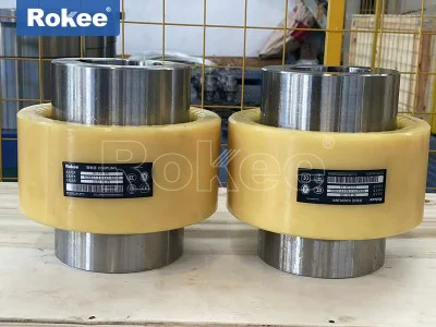
The convenience of installation and maintenance cannot be ignored. The outer gear sleeve of the curved tooth coupling usually has a trumpet shaped tooth end, making it very easy to assemble and disassemble the inner and outer teeth. Some advanced designs are also equipped with intelligent lubrication systems, such as oil collection groove structures - oil collection grooves are machined in the outer gear shaft holes, and oil holes are drilled at the bottom of the tooth grooves to communicate with the oil collection grooves. The centrifugal force generated by high-speed operation is used to spray oil into the meshing area, achieving automatic lubrication. This design is particularly suitable for situations where frequent maintenance is inconvenient, and some models can achieve 10000 hours of maintenance free operation.
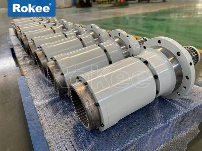
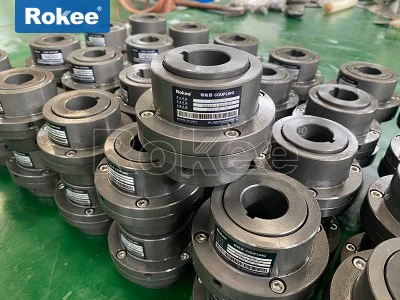
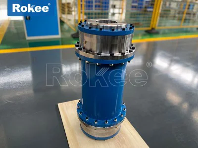
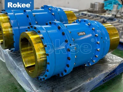
Common series include multiple models such as GICL, GIICL, GCLD, WGP, WGC, WGZ, etc. The GICL and GIICL series are basic curved tooth couplings, particularly suitable for low-speed and heavy-duty working conditions, such as metallurgy, mining, lifting and transportation industries. The GIICL type is further divided into Type I and Type II: Type I adopts a separated sealing end, allowing for larger radial displacement and adapting to Y, J1, and Z1 axial extensions; Type II is an integral sealed end with a more compact structure, suitable for Y and J1 type shaft extensions. GCLD type is a curved tooth coupling with an intermediate shaft, suitable for shaft connections in long-distance transmission. WGP type is a curved tooth coupling with brake discs, commonly used for equipment that requires rapid braking; WGC type is a vertically installed curved tooth coupling designed specifically for transmission systems with vertical installation; The WGZ type is a curved tooth coupling with brake wheels that integrates braking function.
From the perspective of functional configuration, drum gear couplings can be divided into ordinary type, brake type, vertical installation type, intermediate shaft type, etc. ordinary models such as GICL, GIICL, etc. are mainly used for conventional power transmission; Braking types such as WGP, WGZ, NGCL, etc., integrate brake discs or brake wheels and are widely used in equipment such as cranes and mining hoists that require rapid braking; Vertical installation types such as WGC are specifically designed for connecting vertical shaft systems such as vertical pumps and vertical reducers; Intermediate shaft types such as WGJ, GCLD, etc. adapt to the transmission requirements of large shaft spacing by adding intermediate shafts. These different types meet the transmission needs of various complex working conditions, providing users with flexible selection space.
In terms of performance parameter range, the curved tooth coupling covers a wide range of applicable requirements. The nominal torque range is from 0.4kN · m to 4500kN · m, which can meet different torque requirements from small equipment to heavy machinery; The diameter range of the shaft hole is from 16mm to 1040mm, suitable for various shaft diameters; The maximum allowable speed can reach 4000r/min, which is suitable for low-speed heavy-duty situations and can also meet some high-speed transmission requirements.
In the field of mechanical power transmission, shaft couplings serve as critical intermediate components that bridge driving and driven shafts, enabling efficient torque transfer while accommodating unavoidable misalignments that arise from manufacturing tolerances, assembly errors, thermal expansion, operational vibration, and mechanical wear. Among the diverse range of coupling designs available, the curved tooth coupling stands out as a highly versatile and robust solution, widely adopted across heavy-duty and precision mechanical systems due to its unique combination of high torque capacity, flexible misalignment compensation, and long-term operational stability. Unlike rigid couplings that demand perfect shaft alignment and offer no tolerance for positional shifts, or some flexible couplings that sacrifice load-bearing capability for flexibility, the curved tooth coupling strikes a balanced compromise between rigidity and adaptability, making it suitable for applications where consistent power delivery, durability, and resistance to harsh operating conditions are non-negotiable.
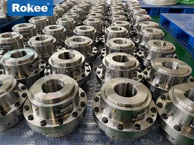
At its core, the curved tooth coupling operates on the principle of gear meshing with a modified tooth profile, distinguishing it from straight-tooth gear couplings and other flexible coupling variants. The fundamental structural composition of a standard curved tooth coupling consists of two key sub-assemblies: the external toothed hubs and the internal toothed sleeve that connects them. Each external hub is precision-machined with a set of curved, crown-shaped teeth around its outer circumference, designed to mate seamlessly with the matching internal curved teeth formed on the inner surface of the central sleeve. The curved contour of the teeth is not a random geometric feature; it is engineered with a specific radius and profile to allow controlled relative movement between the meshing tooth surfaces during operation, which directly enables the coupling to compensate for multiple forms of shaft misalignment. The external hubs are typically mounted onto the driving and driven shafts via interference fits, keyways, or clamping mechanisms, ensuring a secure and backlash-free connection that prevents slippage under high torque loads. The central sleeve acts as the bridging element, enclosing the meshed tooth pairs and often incorporating sealing features to retain lubricant and prevent the ingress of dust, moisture, debris, or corrosive substances from the surrounding environment. Unlike straight teeth that create point contact or limited line contact during misalignment, the curved teeth of this coupling establish broader, more uniform surface contact, distributing stress evenly across the tooth flanks and reducing localized pressure that can lead to premature wear, fatigue, or failure.
The structural design of curved tooth couplings also incorporates subtle engineering refinements to enhance performance and ease of use. The tooth profile is optimized to minimize friction during relative angular, radial, and axial movement between the connected shafts, reducing energy loss and heat generation during continuous operation. Most standard curved tooth couplings require lubrication to maintain smooth meshing, protect against metal-to-metal abrasion, and extend service life, with the internal cavity of the sleeve designed to hold a consistent supply of grease or oil lubricant. Some variations feature integrated sealing systems, such as rubber gaskets or labyrinth seals, to lock in lubrication and block external contaminants, making them suitable for harsh industrial environments with high levels of dust, moisture, or mild chemical exposure. The overall construction is compact relative to its torque-transmitting capacity, allowing installation in space-constrained mechanical setups where larger coupling designs would be impractical. The materials used for manufacturing are selected based on the intended operational load and environment; high-strength alloy steel is the most common choice for heavy-duty applications, offering exceptional tensile strength, toughness, and resistance to fatigue and impact, while carbon steel is used for general-purpose systems with moderate load requirements. In specialized settings, such as those involving low-temperature operation or mild corrosion, surface treatments like quenching and tempering, phosphating, or passivation are applied to enhance hardness, wear resistance, and anti-corrosion properties without altering the core structural integrity of the coupling.
Curved tooth couplings are categorized into distinct functional types based on structural variations, misalignment compensation capabilities, assembly configurations, and specialized operational features, each tailored to address specific transmission challenges. The most primary classification distinguishes between single curved tooth couplings and double curved tooth couplings, a division that defines the extent of misalignment compensation and load distribution. Single curved tooth couplings feature a single set of curved meshing teeth between one hub and the central sleeve, offering reliable torque transfer and moderate compensation for angular and axial misalignment. This design is simpler in construction, lighter in weight, and well-suited for applications with relatively minor shaft misalignment and moderate torque loads, such as small to medium-sized industrial machinery, light-duty conveyor systems, and precision equipment where space and weight are considerations. Double curved tooth couplings, by contrast, incorporate two separate sets of curved meshing teeth, with each external hub connecting to the central sleeve via its own independent tooth pair. This dual-meshing design significantly enhances the coupling’s ability to compensate for combined misalignments—simultaneously accommodating angular, radial, and axial shifts—while distributing torque across twice the number of tooth surfaces. The double curved design delivers higher torque capacity, greater flexibility, and improved resistance to offset loads, making it the preferred choice for heavy-duty, high-load industrial systems where shaft misalignment is more pronounced and operational stresses are elevated.
Further classification of curved tooth couplings is based on structural configuration and auxiliary features, expanding their applicability across specialized use cases. Standard non-floating curved tooth couplings are fixed in their axial positioning, ideal for systems where shafts maintain a consistent distance and only require misalignment compensation without axial movement. Floating curved tooth couplings, on the other hand, feature a modified sleeve and hub design that allows limited axial float between the connected shafts, accommodating thermal expansion-induced axial movement and reducing stress on shaft bearings and supporting components, making them suitable for systems with significant temperature fluctuations during operation. Another specialized variant is the curved tooth coupling with integrated brake wheel or brake disc features, designed to combine power transmission and braking functions in a single compact unit, eliminating the need for separate braking components and simplifying mechanical assembly in equipment that requires frequent starting, stopping, or speed regulation. Additionally, curved tooth couplings are classified by their installation and disassembly design, including quick-assembly types that allow tool-free or simplified installation for maintenance efficiency, and heavy-duty reinforced types with thicker tooth profiles, reinforced hubs, and enhanced material strength for extreme load conditions such as mining machinery, large-scale pumping systems, and heavy industrial gearboxes. Each type retains the core curved tooth meshing principle but is adjusted to prioritize specific performance attributes, ensuring compatibility with the unique operational demands of different mechanical systems.
The performance attributes of curved tooth couplings are the direct result of their specialized structural design, setting them apart from other flexible coupling types and establishing their dominance in demanding transmission applications. One of the most prominent performance features is their exceptional high torque transmission capacity, which far exceeds that of elastomeric couplings, jaw couplings, and many other flexible designs of similar physical size. The curved tooth meshing creates a large contact area between mating teeth, enabling efficient transfer of heavy torsional loads without deformation or slippage, even under intermittent shock loads and sudden torque spikes common in industrial machinery. This high torque density allows engineers to use a smaller, more compact coupling to achieve the same load-bearing capability as larger, bulkier alternatives, optimizing machine design and reducing overall system weight and footprint. A second critical performance trait is the ability to compensate for multiple forms of shaft misalignment simultaneously, including angular misalignment (tilt between shaft axes), radial misalignment (parallel offset between shafts), and axial misalignment (end movement along the shaft axis). Unlike some flexible couplings that only address one or two types of misalignment, curved tooth couplings handle combined misalignments smoothly, preventing excessive stress on shafts, bearings, gears, and other connected components, which in turn reduces wear and extends the service life of the entire transmission system.
Durability and operational reliability are also hallmark performance features of curved tooth couplings, especially in continuous industrial operation. The uniform stress distribution across curved tooth surfaces minimizes tooth fatigue and pitting, common failure modes in straight-tooth couplings under repeated load cycles. The robust material construction and hardened tooth surfaces resist abrasion, impact damage, and deformation, even in harsh operating environments with heavy vibration, temperature extremes, and exposure to industrial contaminants. Properly lubricated and maintained curved tooth couplings exhibit long service intervals and low maintenance requirements, reducing downtime and operational costs for industrial facilities. Additionally, these couplings offer consistent transmission efficiency with minimal energy loss, as the smooth curved tooth meshing reduces friction and eliminates excessive backlash that can cause vibration, noise, and inconsistent power delivery. Unlike some flexible couplings that experience gradual performance degradation due to elastomer wear or component fatigue, curved tooth couplings maintain stable performance over extended periods, providing reliable torque transfer and misalignment compensation without progressive loss of function. They also exhibit good high-speed operational stability, with balanced design and precision machining minimizing rotational imbalance and vibration at elevated operating speeds, making them suitable for both low-speed, high-torque applications and moderate-speed industrial drive systems.
It is important to note that the performance of curved tooth couplings is influenced by proper installation, alignment, and maintenance practices, even though they are more forgiving of misalignment than rigid couplings. Optimal performance requires initial alignment within the coupling’s designed tolerance range, regular lubrication to maintain smooth tooth meshing, and periodic inspection for signs of wear, tooth damage, or seal degradation. Overloading the coupling beyond its rated torque capacity, operating at speeds exceeding its design limits, or exposing it to highly corrosive or abrasive substances without appropriate protection will compromise performance and shorten service life. However, when used within their specified operational parameters, curved tooth couplings deliver consistent, reliable performance that makes them indispensable in a wide range of industrial sectors, where their unique combination of strength, flexibility, and durability addresses critical transmission challenges that other coupling designs cannot adequately solve.
The versatile performance and structural adaptability of curved tooth couplings make them widely applicable across nearly every heavy industrial and manufacturing sector, as well as precision mechanical engineering fields. In heavy machinery and mining equipment, they are extensively used in conveyor systems, crushing machines, grinding mills, and drilling rigs, where their high torque capacity and ability to withstand severe vibration, shock loads, and moderate misalignment are essential for continuous operation in rugged outdoor and underground environments. The mining and mineral processing industry relies on these couplings to transfer power between large electric motors and heavy mechanical components, ensuring uninterrupted material handling and processing even under extreme load conditions. In the metallurgical and steel manufacturing industry, curved tooth couplings are integrated into rolling mills, furnace equipment, material handling systems, and metal forming machinery, where they accommodate thermal expansion-induced shaft movement and transmit heavy torque required for shaping and processing metal materials, while resisting high temperatures and industrial dust exposure.
The petrochemical and chemical processing industry also utilizes curved tooth couplings extensively, particularly in pumping systems, compressor drives, fan assemblies, and rotary machinery. Their sealed construction prevents lubricant leakage and blocks corrosive chemical fumes and moisture from entering the meshing teeth, ensuring reliable operation in potentially hazardous and corrosive environments. The ability to handle moderate misalignment is critical in these applications, as pipeline pressure changes and thermal cycling can cause slight shifts in pump and motor shaft positioning. In the power generation sector, including thermal power plants, hydroelectric facilities, and wind turbine drive systems, curved tooth couplings are used in turbine drives, generator sets, cooling water pump systems, and auxiliary power equipment, providing reliable torque transfer between large rotating components while compensating for misalignment caused by foundation settlement, thermal expansion, and operational vibration. Their high durability and low maintenance needs are especially valuable in power generation facilities, where unplanned downtime can result in significant operational losses and supply disruptions.
Beyond heavy industry, curved tooth couplings find widespread use in general manufacturing, automotive production, marine engineering, and construction machinery. In automotive manufacturing plants, they are integrated into assembly line conveyors, robotic welding equipment, metal stamping machines, and paint shop machinery, offering consistent power delivery and misalignment compensation for high-volume production systems that operate continuously for extended shifts. Marine applications include shipboard propulsion systems, deck machinery, pumping systems, and auxiliary equipment, where the coupling’s resistance to salt spray, moisture, and mechanical shock makes it suitable for the harsh marine environment. Construction machinery such as excavators, bulldozers, concrete mixers, and pumping equipment relies on curved tooth couplings to transfer power from engines to hydraulic systems and drive components, withstanding the heavy shock loads and frequent misalignment associated with mobile construction equipment. Additionally, they are used in precision industrial machinery such as machine tools, textile manufacturing equipment, printing presses, and packaging machinery, where their compact design, low vibration, and consistent torque transfer support high-precision manufacturing processes that require smooth, reliable power delivery.
In summary, the curved tooth coupling represents a masterful engineering solution that balances high load-bearing capacity, flexible misalignment compensation, and long-term durability, filling a critical niche in the mechanical power transmission landscape. Its unique curved gear tooth design enables efficient torque transfer while accommodating the inevitable shaft positional shifts that occur in real-world mechanical systems, avoiding the limitations of rigid couplings and the load constraints of many flexible coupling alternatives. The diverse classifications of curved tooth couplings, ranging from single to double meshing designs, floating to fixed configurations, and standard to heavy-duty variants, ensure that there is a suitable design for nearly every industrial application, from light-duty precision machinery to heavy-duty mining and metallurgical equipment. The core performance advantages—high torque density, multi-axis misalignment compensation, exceptional durability, and stable operational efficiency—solidify its status as a preferred coupling choice across global industries. As mechanical engineering continues to evolve toward more compact, efficient, and durable power transmission systems, the curved tooth coupling will remain a fundamental component, adapting to new operational demands while retaining its core design principles that have proven effective across decades of industrial use. Its enduring relevance stems from its ability to solve practical transmission challenges, reduce mechanical stress and wear, and enhance the overall reliability and service life of complex mechanical systems in every corner of the industrial world.