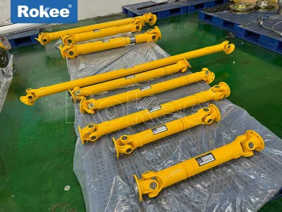
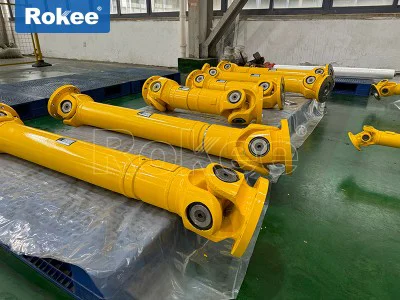
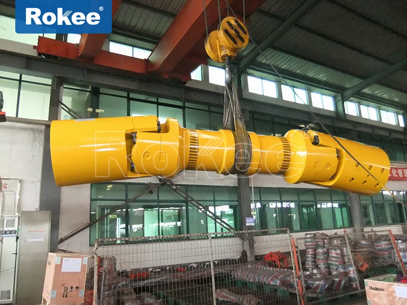
Universal Couplings
Universal coupling is a mechanical device that achieves non collinear transmission of two axes through a special mechanism, and can stably transmit torque and motion at an axis angle of 5 °-45 °. Its core function is to dynamically compensate for angle deviation, while also serving as a buffer for vibration reduction and improving the dynamic performance of the shaft system.
As a key component in mechanical transmission systems, universal couplings play an irreplaceable role in modern industrial equipment. It can solve the problem of power transmission when the axis is not centered or there is an angle, and is widely used in various fields from heavy machinery to precision equipment.
Universal joint is a mechanical component used to connect two shafts (active shaft and passive shaft) in different mechanisms. Its core function is to enable the two shafts to achieve continuous rotation and reliably transmit torque and motion without being on the same axis and with an axis angle. This unique performance makes it an indispensable component of mechanical transmission systems, especially suitable for situations where axial displacement is inevitable due to design, installation, or operation.
From the perspective of structural characteristics, the most significant advantage of universal couplings is their large angular compensation capability. The allowable angle between the two axes of universal couplings with different structural forms is generally between 5 ° -45 °, which provides great flexibility for mechanical design. Meanwhile, universal couplings usually have the characteristics of compact structure and high transmission efficiency, which can achieve efficient power transmission in limited space. In high-speed and heavy-duty power transmission, certain types of universal couplings also have the functions of buffering, damping, and improving the dynamic performance of the shaft system, which is crucial for protecting mechanical equipment and extending its service life.
The basic components of a universal joint include two universal joint forks and a cross shaft assembly (taking the cross shaft type as an example). The joint is composed of two halves, which are respectively connected to the driving shaft and the driven shaft. Generally, most power machines are connected to the working machine through couplings. This structure enables the coupling to operate normally with a certain offset between the shafts, without the need for precise alignment, greatly reducing the difficulty of installation and debugging.
From the perspective of material selection, universal couplings are usually made of high-strength materials such as 45 steel, 45 forged steel, 40 chromium or cast iron to ensure sufficient strength and durability. After appropriate heat treatment processes, these materials can meet the mechanical performance requirements under different working conditions. For special environments such as corrosive media or high temperature conditions, stainless steel or other special alloy materials may also be used.
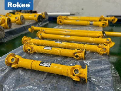
The universal joint in modern industrial applications has developed into various structural forms, including cross shaft type, ball cage type, ball fork type, convex block type, ball pin type, ball joint type, ball joint plunger type, three pin type, trident rod type, three ball pin type, hinge rod type, etc. Among them, the most commonly used is the cross axis type, followed by the cage type. These different types of universal couplings have their own characteristics and are suitable for different application scenarios and working conditions.
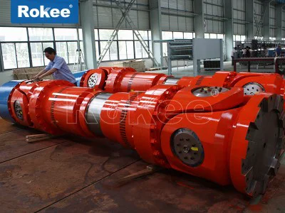
In practical applications, universal couplings can be divided into four specifications based on the magnitude of the transmitted torque: heavy, medium, light, and small. Heavy duty universal couplings are mainly used in heavy industries such as metallurgy and mining, and can transmit extremely high torque; Small universal couplings are commonly used in precision instruments, small machinery, and other applications, emphasizing precision and flexibility rather than torque capacity.
The reason why universal couplings can transmit power in the presence of an angle between their axes is due to their unique kinematic principles and intricate mechanical structure. A deep understanding of its working principle is crucial for the correct selection, use, and maintenance of universal couplings. The core function of a universal joint is to solve the problem of axis misalignment, which may include three basic situations: axial displacement (two axis lines parallel but not on the same straight line), radial displacement (two axis lines intersecting but not on the same straight line), and angular displacement (two axis lines at a certain angle). Universal couplings can effectively compensate for these displacements, ensuring the continuity and stability of power transmission.
The cross axis universal joint, as the most typical type, consists of two universal joint forks and a cross axis in its basic structure. The four ends of the cross shaft are connected to two fork heads through needle roller bearings, which allows the two connected shafts to produce relative angular displacement in multiple directions. When the driving shaft rotates, the driven shaft is driven to rotate by the cross shaft, and torque can be transmitted even when there is an angle between the two shafts. However, the single cross axis universal joint has an inherent characteristic: when there is an angle between the two shafts, the angular velocity of the driven shaft will periodically change, resulting in speed fluctuations and additional dynamic loads. The magnitude of this fluctuation is proportional to the angle between the two axes, and when the angle is 30 °, the velocity fluctuation can reach about 30%. To solve this problem, a dual universal joint arrangement is commonly used in practical applications, which eliminates velocity fluctuations and achieves constant speed transmission through specific spatial geometric relationships (such as placing the fork heads at both ends of the intermediate shaft in the same plane and making the angle between the intermediate shaft and the main and driven shafts equal).
The ball cage universal joint adopts a completely different constant velocity principle. Its core structure consists of an inner ball cage, an outer ball cage, a retaining frame, and a force transmitting steel ball. Through precise spherical geometric relationships, the force transmitting steel ball is always located on the bisector of the angle between the two axes, thus achieving true constant speed transmission. The advantages of the ball cage universal joint are smooth transmission, high efficiency, a large allowable working angle (up to 45 °), and high speed capability. Therefore, it is widely used in automotive drive shafts and other applications. Another common type of constant velocity universal joint is the ball fork universal joint, which has a relatively simple structure but strong load-bearing capacity and is commonly used in heavy-duty vehicles.
From a dynamic perspective, the universal joint not only transmits the main torque during operation, but also generates additional bending moments and axial forces due to the angle between the axes. These additional loads increase rapidly with the increase of the angle, so in practical applications, the axis angle should be minimized as much as possible, generally not exceeding 15 ° -20 °. For situations that require large angle transmission, a specially designed universal joint should be selected, and special support structures should be considered to withstand these additional loads.
The lubrication system of the universal joint is also a core part of its design. Good lubrication can significantly reduce wear and prolong service life. Modern universal couplings often use lithium based grease centralized lubrication systems. For high temperatures or special environments, synthetic grease or special lubricants need to be selected. Some high-performance universal couplings are also equipped with sealing systems to prevent lubricant leakage and contamination from entering, which is particularly important in harsh working conditions such as mining and metallurgy.
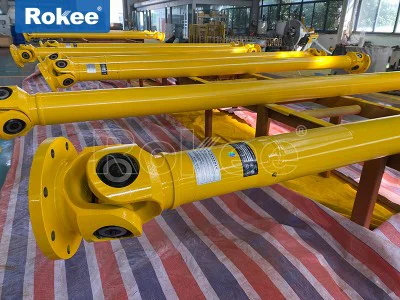
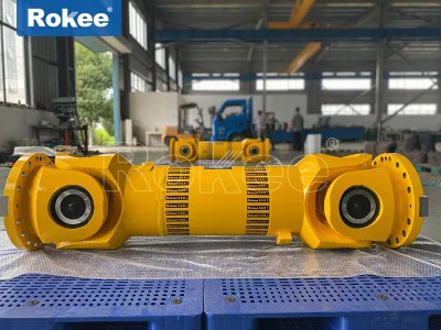
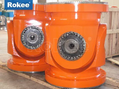
The cross axis universal joint is the most traditional and common type, with a relatively simple structure consisting of two fork shaped joints and a cross axis. The angle change is achieved through needle roller bearings on the cross axis. This type of coupling has the characteristics of high load-bearing capacity, reliable structure, and easy maintenance, making it particularly suitable for heavy machinery. According to the different designs of the bearing seat and cross head, the cross shaft universal joint can be divided into various forms: SWC type integral cross head universal joint (JB/T 5513-2006), SWP type partial bearing seat cross shaft universal joint (JB/T 3241-2005), SWZ type integral bearing seat cross shaft universal joint (JB/T 3242-1993), etc. Among them, the SWP type split bearing seat cross axis universal joint is made of forged steel material and follows the JB3241-91 standard. Its rotation diameter covers 160-640mm, and the nominal torque range is 16-1250kN · m. It achieves displacement compensation in all directions through the split bearing seat structure, and the axis angle can reach 10 ° (5 ° for G type). It is mainly used for the transmission shaft connection of heavy equipment such as steel rolling machinery and lifting and transportation machinery.
A universal coupling, also commonly referred to as a universal joint, is a crucial mechanical component designed to connect two rotating shafts that are not aligned on the same axis, enabling the reliable transmission of torque and rotational motion between them. Unlike rigid couplings that require precise coaxial alignment, universal couplings possess unique structural characteristics that allow them to compensate for angular, axial, and radial misalignments, making them indispensable in a wide range of mechanical transmission systems across various industries. The ability to accommodate misalignments arises from their specialized design, which incorporates flexible joints that can adjust to changes in the relative position of the connected shafts without compromising the efficiency of power transmission or causing excessive wear and tear on the system components. This versatility has made universal couplings a preferred choice in applications where perfect alignment is difficult to achieve, either due to installation constraints, dynamic operational changes, or structural limitations of the machinery.
The basic structure of a universal coupling consists of several core components that work together seamlessly to facilitate torque transmission and misalignment compensation. At the heart of most universal couplings are two yokes, which are fork-shaped components attached to the ends of the two shafts that need to be connected. These yokes are oriented at 90 degrees to each other and are joined by a central cross-shaped component known as a cross shaft or spider. The cross shaft features four trunnions, one at each end of its perpendicular arms, which fit into bearings mounted within the yokes. These bearings, often needle roller bearings or plain bearings, reduce friction between the cross shaft and the yokes, allowing for smooth rotational movement and articulation as the shafts adjust their relative angles. In some designs, the cross shaft may be integrated with a sleeve or housing to provide additional support and protection, while also serving as a containment for lubrication. The yokes are typically secured to the shafts using set screws, keyways, or splined connections, ensuring a tight and secure fit that prevents slippage during torque transmission. Depending on the specific type and application requirements, the structure may also include additional components such as seals to prevent the ingress of dust, dirt, and moisture, or telescopic sections to accommodate axial displacement between the shafts. The materials used in the construction of universal couplings are carefully selected based on the operational demands, with high-strength alloy steels, carbon steels, and forged steels being the most common choices due to their excellent tensile strength, wear resistance, and fatigue life. For applications requiring corrosion resistance, stainless steel or non-metallic materials may be used, while lightweight materials such as aluminum alloys are preferred in scenarios where weight reduction is a priority.
The performance of a universal coupling is defined by a set of key characteristics that determine its suitability for different applications, including torque capacity, angular compensation range, transmission efficiency, rotational accuracy, wear resistance, and operating speed. Torque capacity is one of the most critical performance parameters, referring to the maximum amount of torque that the coupling can transmit without experiencing permanent deformation or failure. This capacity is influenced by factors such as the material strength of the cross shaft and yokes, the size and design of the bearings, and the overall dimensions of the coupling. Universal couplings are available in a wide range of torque capacities, from small units capable of transmitting a few newton-meters to heavy-duty models designed to handle thousands of newton-meters, making them suitable for both light and heavy industrial applications. Angular compensation range is another essential performance feature, describing the maximum angle at which the two connected shafts can be misaligned while still maintaining efficient torque transmission. Most standard universal couplings can accommodate angular misalignments between 5 degrees and 45 degrees per joint, with some specialized designs capable of handling even larger angles when configured as double joints. Axial and radial compensation capabilities are also important, allowing the coupling to adjust for small amounts of axial movement (end play) and radial offset between the shafts, which may occur due to thermal expansion, vibration, or installation errors.
Transmission efficiency is a measure of how effectively the coupling transfers power from the input shaft to the output shaft, with minimal energy loss. High-quality universal couplings typically exhibit transmission efficiencies between 98% and 99.8%, making them highly efficient components in mechanical systems. Energy loss in universal couplings is primarily due to friction between the moving parts, such as the cross shaft and bearings, which can be minimized through proper lubrication and the use of high-performance bearing materials. Rotational accuracy refers to the ability of the coupling to maintain a consistent rotational speed between the input and output shafts, without introducing excessive vibration or speed fluctuations. Single universal joints may exhibit a phenomenon known as angular velocity fluctuation, where the output shaft speed varies slightly as the cross shaft rotates, especially at larger angular misalignments. This fluctuation can cause vibration and noise in the system, which is why double universal joints are often used in applications requiring high rotational accuracy, as they cancel out these speed variations by utilizing two joints arranged in series with their yokes phased correctly. Wear resistance is another important performance characteristic, as the moving components of the coupling are subject to continuous friction and load during operation. Proper lubrication, the use of wear-resistant materials, and robust bearing designs all contribute to extending the service life of the coupling and reducing maintenance requirements. Operating speed is the maximum rotational speed at which the coupling can operate safely without experiencing excessive vibration, heat buildup, or component failure. This parameter is influenced by the design of the coupling, the quality of the bearings, and the balance of the rotating components, with high-speed applications typically requiring precision-machined couplings with balanced cross shafts and yokes.
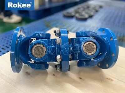
Universal couplings are available in a variety of types, each designed to meet specific application requirements based on factors such as misalignment needs, torque capacity, operating speed, and environmental conditions. The most common type is the cross shaft universal coupling, also known as the Hooke's joint, which features the basic structure of two yokes and a cross shaft described earlier. Cross shaft universal couplings are further categorized into different subtypes based on their design variations, such as integral fork and split fork designs. Integral fork couplings have a one-piece fork head, which enhances strength and eliminates the risk of bolt loosening or breakage, making them suitable for heavy-duty applications. Split fork couplings, on the other hand, have a two-piece fork head that can be disassembled, allowing for easier installation and maintenance, particularly in situations where the coupling is mounted in a confined space. Another subtype of cross shaft universal coupling is the telescopic universal coupling, which incorporates a splined connection between the yoke and the shaft, enabling axial displacement compensation in addition to angular misalignment. This type is commonly used in applications where the distance between the shafts varies during operation, such as in automotive drive shafts.
Constant velocity (CV) universal couplings are another important type, designed to eliminate the angular velocity fluctuation associated with single cross shaft couplings, ensuring that the input and output shafts rotate at the same speed regardless of the angular misalignment. CV couplings achieve this through the use of a spherical inner race, outer race, and a set of ball bearings or rollers that are positioned in a way that maintains a constant velocity ratio. The most common CV coupling designs include the ball cage type and the ball fork type. Ball cage CV couplings feature a cage that holds the balls in place between the inner and outer races, allowing for smooth articulation and constant velocity transmission, even at large angular misalignments. These are widely used in front-wheel-drive vehicles, where they connect the transmission to the front wheels, accommodating both the angular movement of the steering system and the up-and-down movement of the suspension. Ball fork CV couplings have a simpler design, with a fork-shaped inner component and a spherical outer component that contains the balls, making them more cost-effective but with lower torque capacity and speed range compared to ball cage types. They are commonly used in agricultural machinery and low-speed industrial applications.
Ball hinge universal couplings are a specialized type that uses a spherical articulated structure instead of a cross shaft, providing higher radial load capacity compared to cross shaft couplings—often up to 52% higher. These couplings are available in single ball hinge and double ball hinge designs, with double ball hinge models offering greater compatibility but slightly lower torque transmission capability. They are particularly suitable for extreme operating conditions, such as high radial loads or harsh environments where other coupling types may fail. Other specialized types of universal couplings include three-pin or three-fork couplings, which are designed to handle large angular deflections, making them ideal for applications such as marine propulsion systems. Cam and follower universal couplings, also known as hinge rod couplings, have a compact structure but limited misalignment compensation capability, making them suitable for specific industrial equipment where space is constrained and misalignment is minimal. Flexible universal couplings, which incorporate elastic elements such as rubber or metal discs, combine the misalignment compensation capabilities of universal couplings with the vibration damping properties of flexible couplings, making them suitable for high-speed or precision transmission systems where vibration reduction is critical.
The wide range of structural designs and performance characteristics of universal couplings makes them suitable for a diverse array of applications across numerous industries. In the automotive industry, universal couplings are essential components in drive train systems, particularly in rear-wheel-drive and four-wheel-drive vehicles. In rear-wheel-drive vehicles, a single or double cross shaft universal coupling is used to connect the transmission output shaft to the drive axle, accommodating the angular misalignment between the two components as the vehicle suspension moves. In front-wheel-drive vehicles, CV universal couplings are used to connect the transaxle to the front wheels, allowing for both power transmission and steering movement without speed fluctuations. Universal couplings are also used in motorcycle drive shafts, heavy-duty trucks, and buses, where they handle high torque loads and dynamic misalignments.
Heavy industrial applications represent another major area of use for universal couplings, particularly in sectors such as metallurgy, mining, and construction. In metallurgical plants, cross shaft universal couplings are used in rolling mill systems, where they transmit large torques between the drive motors and the rolling rolls, accommodating the angular misalignment caused by roll adjustments and thermal expansion. These couplings must be capable of withstanding high temperatures, heavy loads, and harsh environmental conditions, such as dust and debris, making heavy-duty integral fork designs the preferred choice. In the mining industry, universal couplings are used in crushers, conveyors, and excavators, where they handle high torque and shock loads while compensating for misalignments caused by the rugged operating environment. Construction machinery, such as cranes, bulldozers, and loaders, also rely on universal couplings to transmit power between engines, hydraulic pumps, and other components, accommodating the dynamic misalignments that occur during operation.
The marine and offshore industry also utilizes universal couplings in various applications, including ship propulsion systems, marine pumps, and offshore platform equipment. In ship propulsion systems, universal couplings connect the ship's engine to the propeller shaft, compensating for the angular misalignments caused by hull flexing and wave-induced motion. These couplings must be designed to withstand corrosive marine environments, high torque loads, and continuous operation, often incorporating stainless steel components and robust sealing systems to prevent seawater ingress. Offshore platforms use universal couplings in power generation systems, cranes, and material handling equipment, where they provide reliable torque transmission in harsh offshore conditions.
Precision manufacturing and automation industries rely on specialized universal couplings, such as CV couplings and flexible universal couplings, to ensure high rotational accuracy and vibration reduction. In machine tools, such as lathes, milling machines, and CNC routers, universal couplings connect the drive motors to the spindles and tool heads, maintaining precise rotational speeds and minimizing vibration to ensure high-quality machining. Robotics and automation systems use small, precision universal couplings in joint mechanisms, allowing for smooth and accurate movement of robotic arms and end effectors. These couplings are often made from lightweight materials and feature high-precision bearings to meet the strict accuracy requirements of automated systems.
The energy sector, including wind power, hydropower, and thermal power generation, also uses universal couplings in various applications. In wind turbines, universal couplings connect the turbine rotor to the generator, accommodating the angular misalignments caused by wind-induced rotor movement and tower flexing. These couplings must be designed to handle variable torque loads and operate in harsh outdoor environments, often featuring corrosion-resistant materials and low-maintenance designs. Hydropower plants use universal couplings in turbine and generator systems, transmitting power between the water turbine and the generator while compensating for misalignments caused by thermal expansion and structural movement. Thermal power plants use universal couplings in boiler feed pumps, fans, and conveyor systems, providing reliable torque transmission in high-temperature environments.
Agricultural machinery, such as tractors, harvesters, and irrigation systems, also relies on universal couplings for power transmission. In tractors, universal couplings connect the engine to various implements, such as plows, harrows, and mowers, accommodating the angular misalignments caused by uneven terrain and implement movement. These couplings are typically designed to be robust, easy to maintain, and capable of handling shock loads, making them suitable for the demanding conditions of agricultural operations. Irrigation systems use universal couplings in pump and motor connections, ensuring reliable water delivery in agricultural fields.
In addition to these major industries, universal couplings are also used in a variety of general industrial applications, such as pumps, fans, compressors, and conveyor systems. In pumps and fans, universal couplings connect the drive motors to the impellers and rotors, compensating for misalignments caused by installation errors and thermal expansion. Compressors use universal couplings in drive systems, handling high torque loads and maintaining efficient power transmission. Conveyor systems use universal couplings to connect drive motors to conveyor rollers, accommodating misalignments caused by conveyor belt tension and structural movement.
The selection of the appropriate universal coupling for a specific application requires careful consideration of several factors, including torque requirements, angular misalignment range, operating speed, axial and radial displacement needs, environmental conditions, and maintenance requirements. For heavy-duty applications with high torque and large angular misalignments, cross shaft universal couplings with integral forks are typically the best choice. For high-speed, precision applications requiring constant velocity transmission, CV couplings are preferred. For applications requiring vibration damping, flexible universal couplings with elastic elements are suitable. Environmental factors, such as temperature, humidity, and corrosion, also influence material selection, with stainless steel and non-metallic materials being used in corrosive environments and high-temperature alloys being used in extreme temperature conditions.
Proper maintenance is essential to ensure the long-term performance and reliability of universal couplings. Regular lubrication of the bearings and cross shaft is critical to reduce friction and wear, with the type of lubricant selected based on the operating temperature and load conditions. Seals should be inspected regularly to ensure they are intact and functioning properly, preventing the ingress of contaminants that can cause premature wear. The coupling should also be inspected for signs of damage, such as cracks in the yokes or cross shaft, excessive play in the bearings, or wear on the trunnions. Any damaged components should be replaced promptly to prevent catastrophic failure of the coupling and the connected machinery.
In conclusion, universal couplings are versatile and essential mechanical components that play a critical role in enabling torque transmission between misaligned shafts across a wide range of industries. Their unique structural design, which incorporates yokes, a cross shaft, and bearings, allows them to compensate for angular, axial, and radial misalignments while maintaining high transmission efficiency and reliability. The various types of universal couplings, including cross shaft, CV, ball hinge, and flexible designs, are tailored to meet the specific requirements of different applications, from heavy-duty industrial machinery to precision automation systems. With ongoing advancements in material science and manufacturing technology, universal couplings continue to evolve, offering higher torque capacities, greater misalignment compensation, improved durability, and lower maintenance requirements. As industries continue to demand more efficient, reliable, and flexible mechanical systems, the importance of universal couplings in modern engineering and manufacturing will only continue to grow.