Double Diaphragm Couplings
Double diaphragm coupling is an advanced metal elastic element flexible coupling, which occupies an important position in modern industrial transmission systems with its unique structure and excellent performance.
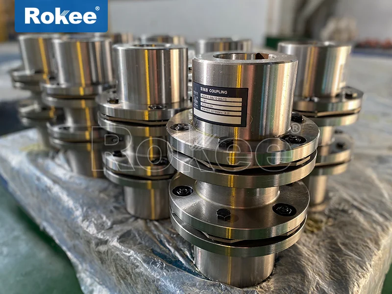
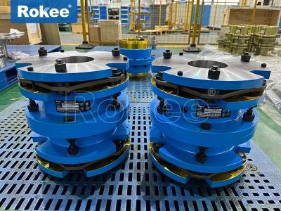
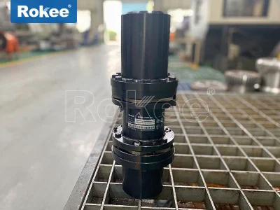
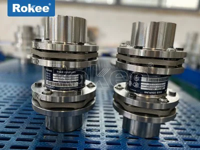
Double diaphragm coupling is a flexible coupling device with multi-layer stainless steel diaphragm group as the core component, which complies with the mechanical industry standard JB/T9147-1999. Its basic structure consists of the following parts:
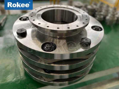
Metal diaphragm group: usually made of multiple layers of stainless steel thin plates stacked together, it is the core elastic element of the coupling. Each group of membranes is composed of several stacked pieces, divided into two main types: linkage type and integral piece with different shapes.
Connecting components: including staggered bolt assemblies, flanges, and buffer sleeves. Bolts are usually inserted from the outside of the small hole on the flange, pass through the diaphragm hole, and then exit from the outside of the large hole on the other side of the flange. After fitting with a buffer sleeve and elastic washer, tighten the nut.
Shaft sleeve or hub: used to connect the transmission shaft and diaphragm group, usually designed with different connection methods such as keyway, clamping mechanism or cone sleeve to adapt to various shaft end forms.
The working principle of the double diaphragm coupling is based on the elastic deformation characteristics of the metal diaphragm. When the driving shaft rotates, the torque is transmitted to the diaphragm through the bolt group, and the diaphragm undergoes elastic deformation and transmits the torque to the driven shaft. This design enables it to effectively compensate for the relative displacement between the two axes:
Axial displacement compensation: The diaphragm can undergo bending deformation along the axis direction, absorbing axial installation errors.
Radial displacement compensation: The diaphragm group can generate radial elastic deformation to adapt to the parallel deviation between the two axes.
Angular displacement compensation: The diaphragm can withstand a certain degree of deflection and compensate for the angular deviation between the two axes.
Compared with single diaphragm couplings, the dual diaphragm design significantly improves compensation capability through the synergistic effect of two sets of diaphragms. Single diaphragm couplings are not very suitable for eccentric working conditions, while double diaphragm couplings can bend in different directions simultaneously, more effectively compensating for complex deviations.
The double diaphragm coupling combines multiple excellent performances, making it an ideal choice for many industrial applications:
Excellent transmission performance
High torque rigidity: The static torsional stiffness can reach 450-3400N · m/rad, which can transmit large torque without producing significant torsional angles.
Zero backlash: The metal diaphragm connection ensures seamless transmission, making it particularly suitable for servo systems that require precise position control.
Efficient transmission: With a transmission efficiency of up to 99.86% and minimal energy loss, it outperforms most other types of couplings.Excellent environmental adaptability
Corrosion resistance: The stainless steel membrane and surface treatment give it acid, alkali, and corrosion resistance, making it suitable for harsh environments such as chemical and marine industries.
Wide temperature operation: It can work stably within the temperature range of -80 ℃ to+300 ℃ and adapt to extreme temperature conditions.
Fatigue resistance: Metal elastic components have high strength and long service life, far superior to non-metallic elastic component couplings.Significant operational advantages
Maintenance free design: No lubrication or sealing required, reducing downtime and maintenance costs.
Vibration and noise reduction: The elastic properties of the diaphragm can absorb vibrations and impacts, reducing system noise.
Compact structure: small size, light weight, saving installation space, especially suitable for applications with limited space.Safety and reliability
Overload protection: When the torque exceeds the design value, the diaphragm will undergo significant deformation, providing a certain degree of overload protection.
Failure safety: Even if the diaphragm is damaged, the coupling can usually maintain short-term transmission to avoid sudden equipment shutdown.
Balance performance: After precision dynamic balancing treatment, the maximum speed can reach 6000r/min, suitable for high-speed operation.
Compared with traditional gear couplings, double diaphragm couplings have no relative sliding parts, do not require lubrication and sealing, are basically maintenance free, and are relatively easy to manufacture. They have replaced gear couplings in many applications. In industrialized countries, the application of diaphragm couplings has become very common.
Multiple models and series of double diaphragm couplings have been developed based on specific structures and application requirements, with common classifications including:
Classified by structural form
JMI type diaphragm coupling: Basic double diaphragm coupling, suitable for general transmission applications.
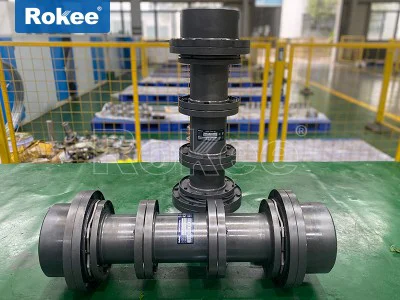
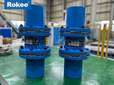
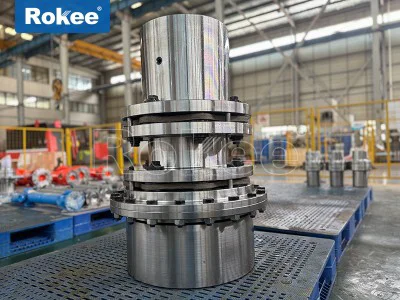
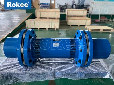
JMIJ type diaphragm coupling: an improved version with an extended intermediate section, which can achieve longer wheelbase connections.
JMII type diaphragm coupling: heavy-duty design, suitable for high torque transmission.
JMIIJ type diaphragm coupling: heavy-duty with extended middle section, meeting the requirements of high torque and long wheelbase.Classified by connection method
Keyway connection type: The most common connection method is to connect the shaft and coupling through keys and keyways.
Expansion sleeve connection type: using the fastening force of the expansion sleeve to achieve connection, suitable for situations where it is inconvenient to process keyways.
Cone sleeve connection type: tight connection is achieved through a conical sleeve, which is easy to install and disassemble.
Clamping type connection: The shaft surface is directly clamped by bolts, which is easy to install and does not damage the shaft surface.Special Design Series
SJM series: designed specifically for high temperature, high speed, and corrosive environments, using special materials and structures.
ZJM series: cone sleeve connection type, especially suitable for occasions that require frequent disassembly.
TJM series: External clamping design, the most convenient installation.
MCSLC series: High precision servo specific type, with extremely high torsional stiffness and positioning accuracy.
Each series of double diaphragm couplings has different torque capacity, speed limit, compensation capability, and size specifications. Users can choose the most suitable model according to their specific application needs. It is worth noting that in most practical applications, the intermediate shaft type design (i.e. double diaphragm structure) is adopted to improve the performance of two axis offset compensation.
Double diaphragm couplings are widely used in many industrial fields due to their excellent performance:
General industrial equipment
Pump equipment, especially high-power chemical pumps, boiler feed pumps, etc., utilize their characteristics of corrosion resistance and good sealing.
Fan system: used for cooling tower fans, industrial ventilation equipment, etc., to leverage its vibration reduction and noise reduction advantages.
Compressor: Provides reliable shaft connections in air compressors and refrigeration compressors.Heavy Industry and Energy
Petroleum machinery: oilfield drilling equipment, oil pumps, etc., utilizing their corrosion resistance and maintenance free characteristics.
Metallurgical equipment: high temperature and heavy load applications such as rolling mills and continuous casting machines.
Generator set: The connection between the steam turbine, water turbine, and generator needs to withstand high speed and high power.Precision and special equipment
Aviation and naval vessels: helicopter transmission system, high-speed power transmission for naval vessels, requiring high reliability and lightweight.
Printing machinery: occasions that require precise transmission and no reverse clearance.
Textile machinery: smooth transmission under high-speed operation.
Servo system: high-precision positioning equipment such as robots and CNC machine tools.Special environmental applications
Chemical equipment: Suitable for chemical pumps, mixing equipment, etc. due to its acid and alkali resistance and anti-corrosion properties.
Mining machinery: provides reliable transmission under harsh working conditions.
Tracked vehicles: Suitable for working environments with high impact and vibration.The double diaphragm coupling is particularly suitable for the following working conditions:
In situations where compensation for significant axis deviation is required
High speed and high-power transmission system
Corrosive or high-temperature environment
Require maintenance free and long-lasting applications
Precision machinery that requires precise transmission
In practical applications, double diaphragm couplings have successfully replaced many traditional couplings, such as hydraulic couplings. For example, in the cooling tower fan system, the motor and fan connected by a double diaphragm coupling after removing the liquid coupling not only transmit large torque, but also automatically correct the concentricity deviation of the shaft system, achieving simple and smooth rotation.
Proper installation and maintenance are key to ensuring optimal performance and extended service life of the double diaphragm coupling.
Installation steps and precautions
Preparation before installation
Clean the shaft end and coupling inner hole, remove oil stains and burrs
Check the integrity of each component to ensure there are no missing or damaged parts
Apply a thin layer of engine oil or lubricant to the inner holes of the shaft and coupling for easy installationShaft alignment adjustment
Use a dial gauge to check the radial and axial deviations of the two axes
Ensure that the deviation is within the allowable range of the coupling (usually radial ≤ 0.2mm, angular ≤ 0.5 °)
When multiple deviations exist simultaneously, the allowable value should be halvedBolt installation
Install the bolts in the correct direction: Insert them from the outside of the small hole on the flange, pass through the membrane hole, and then exit through the large hole on the other side of the flange
Step by step tightening of bolts: First pre tighten the diagonal direction with 1/4 of the specified torque, then apply 1/2 of the torque, and finally tighten with full torque
Use a torque wrench to ensure that the bolt reaches the specified torque (e.g. M5 bolt is usually 7.8N · m)
Check the clearance between the bolt and the flange fitting section (0.20-0.30mm)Gap inspection
Measure the gap between two sets of membranes, which should be the actual thickness of the membranes plus 0.5mm
Too small a gap can lead to installation difficulties and abnormal noise during operation
Excessive clearance can cause excessive deformation of the membrane and shorten its lifespanFinal inspection
Manually rotate the coupling to check for smoothness
Check if all fasteners are secure
If necessary, apply adhesive on the outer surface of the bolt to prevent looseningKey installation parameter control
The clearance between the flange and the diaphragm should be controlled within the range of 0.20-0.30mm
Gap between buffer sleeve and membrane rivet inner hole: 0.5-0.7mm
Axial propulsion position: Record the initial position of the hub on the shaft to ensure correct installation in place
Bolt tightening sequence: Cross tighten in diagonal direction step by step
Key points of maintenance and upkeep
Regular inspection
Recheck the tightening of all bolts after running one shift
Regularly inspect the membrane for cracks, deformation, or corrosion
Monitor the operation sound, abnormal noise may indicate poor alignment or component damageWear and tear protection
Apply solid lubricants such as molybdenum disulfide between the membranes to reduce micro motion wear
Apply anti-wear coating treatment to the surface of the membrane to extend its lifespan
Check for microcracks around the bolt holesOperation precautions
Avoid long-term overload use
Prevent impact loads caused by operational accidents
Install protective covers at hazardous locations to ensure safetyFault handling
Immediately stop the machine for inspection upon discovering any abnormalities
When replacing damaged membranes, they need to be replaced in groups to maintain balance
When severely damaged, the entire coupling should be replaced
Common problems and solutions
Abnormal noise
Reason: Poor shaft alignment, loose bolts, damaged diaphragm
Solution: Re center, tighten bolts, replace diaphragmPremature failure of membrane
Reason: Axis deviation exceeding limit, overload, corrosive environment
Solution: Adjust alignment, check load, and select corrosion-resistant modelsBolt fracture
Reason: Improper installation, fatigue damage, excessive torque
Solution: Install according to specifications, replace regularly, and check torque
Proper installation and maintenance can extend the lifespan of double diaphragm couplings to several years or even longer. Compared to toothed couplings that require regular lubrication and maintenance, the maintenance free feature of double diaphragm couplings can significantly reduce overall operating costs.
In the realm of modern mechanical power transmission, the double diaphragm coupling stands out as a highly versatile and reliable flexible coupling, engineered to address the inherent challenges of shaft misalignment, torque transmission, and operational stability across diverse industrial settings. Unlike rigid couplings that offer no tolerance for shaft displacement or flexible couplings reliant on non-metallic elastic components prone to wear and aging, the double diaphragm coupling leverages the elastic deformation of precision-engineered metal diaphragms to deliver a unique blend of rigidity, flexibility, and durability. This mechanical component serves as a critical intermediary between driving and driven shafts, facilitating seamless torque transfer while compensating for various forms of misalignment, reducing vibration and shock loads, and maintaining consistent performance even in demanding operating environments. Its design philosophy centers on balancing torsional stiffness for precise power delivery and elastic flexibility for misalignment accommodation, making it a cornerstone component in high-precision, high-speed, and heavy-duty transmission systems worldwide.
At its core, the structural composition of the double diaphragm coupling is meticulously crafted to optimize functional performance, with no redundant parts and a streamlined assembly that prioritizes efficiency and reliability. The primary structural elements consist of two sets of thin, high-strength metal diaphragm groups, two hub assemblies (or shaft sleeves), and a set of high-precision connecting fasteners, typically bolts and washers. The metal diaphragm groups are the heart of the coupling, usually fabricated from multi-layer stacked stainless steel sheets or other alloy steels with exceptional fatigue resistance, tensile strength, and elastic resilience. Each diaphragm is precision-machined to a uniform thickness, with bolt holes and contour profiles designed to distribute stress evenly during deformation, preventing localized fatigue failure that could compromise service life. The two diaphragm groups are positioned symmetrically on either side of the coupling, separated by the intermediate hub or spacer section, creating a dual-diaphragm configuration that distinguishes it from single diaphragm couplings. This symmetrical layout ensures that the coupling can handle combined misalignments—angular, radial, and axial—simultaneously, rather than being limited to single-direction displacement compensation.
The hub assemblies, which connect the coupling to the driving and driven shafts, are designed with multiple mounting configurations to suit different shaft types and installation requirements, ranging from keyway connections and clamping hubs to taper lock bushings. These hubs are machined with high concentricity to ensure a tight, secure fit with the shaft, eliminating backlash and preventing slippage during torque transmission. The connecting fasteners are installed in a staggered or alternating pattern, passing through the diaphragm groups and hubs to create a rigid torque transmission path while allowing the diaphragms to flex freely as needed. Notably, the double diaphragm coupling features no sliding contact surfaces, frictional components, or non-metallic elastic elements such as rubber or plastic, which eliminates the need for lubrication, reduces wear-related degradation, and minimizes maintenance demands. This lubrication-free, maintenance-free structural design is a defining advantage, as it avoids the common issues of lubricant leakage, contamination, and component aging that plague traditional gear couplings, elastomeric couplings, and fluid couplings.
The operational principle of the double diaphragm coupling is rooted in the controlled elastic deformation of the dual metal diaphragm groups. When torque is applied from the driving shaft, it is transferred through the hub to the first diaphragm group, which undergoes slight elastic bending and torsional deformation to absorb initial shock loads. The torque is then transmitted through the intermediate section to the second diaphragm group, which further distributes the load and compensates for any residual misalignment before transferring power to the driven shaft. This sequential, dual-diaphragm deformation mechanism enables the coupling to accommodate three primary types of shaft misalignment: angular misalignment, caused by non-parallel shaft axes; radial misalignment, resulting from parallel shaft offset; and axial misalignment, stemming from shaft end play or thermal expansion. Unlike single diaphragm couplings, which struggle with combined misalignments and often experience uneven stress distribution, the double diaphragm design distributes deformation across two separate diaphragm sets, reducing stress concentration on each individual diaphragm and enhancing overall misalignment compensation capacity. This balanced deformation also minimizes the transmission of vibration between the driving and driven equipment, dampening resonant frequencies and reducing noise levels during operation, which in turn extends the service life of connected bearings, gears, and other precision components.
The performance characteristics of the double diaphragm coupling are tailored to meet the rigorous demands of modern industrial machinery, encompassing torsional rigidity, transmission efficiency, environmental adaptability, and operational longevity. One of its most prominent performance attributes is zero backlash operation, a critical feature for high-precision transmission systems where positional accuracy and rotational synchronization are paramount. The rigid metal-to-metal connection between the diaphragms and hubs eliminates any free play or rotational clearance, ensuring that torque is transmitted instantaneously and without lag, making the coupling ideal for servo-driven systems, CNC machinery, and other precision equipment requiring consistent positioning. Additionally, the coupling boasts exceptionally high transmission efficiency, typically exceeding 99% across its operating range, as the absence of frictional losses and sliding components minimizes energy dissipation. This high efficiency translates to reduced power consumption, lower heat generation, and improved overall system energy performance, particularly in high-speed and high-torque applications.
Torsional stiffness is another key performance metric, with the double diaphragm coupling offering a high degree of static and dynamic torsional rigidity to maintain rotational stability under variable load conditions. This rigidity prevents excessive torsional deflection during acceleration, deceleration, or load spikes, ensuring that the driven equipment operates with consistent speed and torque output. Despite its high rigidity, the coupling retains exceptional flexibility to handle misalignment, striking a delicate balance that few other coupling types can achieve. In terms of environmental adaptability, the all-metal construction of the double diaphragm coupling enables it to perform reliably in extreme conditions, including high and low temperatures, corrosive atmospheres, and dusty or humid industrial environments. The corrosion-resistant alloy materials used in the diaphragms and hubs resist degradation from chemicals, moisture, and oxidation, while the absence of non-metallic parts means the coupling is unaffected by temperature-induced softening, hardening, or cracking. Furthermore, the coupling exhibits excellent fatigue resistance, with the multi-layer diaphragm design distributing cyclic stress to prevent crack propagation, resulting in a long service life even under continuous, high-load operation.
The double diaphragm coupling also offers superior operational reliability, with a fail-safe design that ensures limited functionality even in the rare event of diaphragm damage, preventing catastrophic equipment failure and allowing for controlled shutdowns. Its compact, lightweight construction reduces the overall mass of the transmission system, lowering rotational inertia and minimizing bearing loads on connected shafts, which is particularly beneficial for high-speed machinery. Unlike elastomeric couplings that degrade over time and require frequent replacement, or gear couplings that demand regular lubrication and maintenance, the double diaphragm coupling operates reliably for extended periods with minimal intervention, reducing downtime and operational costs for industrial facilities. Collectively, these performance traits make the double diaphragm coupling a superior alternative to traditional flexible couplings, offering a compelling combination of precision, efficiency, durability, and low maintenance.
Classified by structural design and functional attributes, double diaphragm couplings encompass a range of variants, each optimized for specific application scenarios, load capacities, and installation constraints. The most fundamental classification is based on the presence or absence of an intermediate spacer section, distinguishing between standard double diaphragm couplings and long-span double diaphragm couplings. Standard double diaphragm couplings feature a compact design with a short intermediate section, ideal for applications with limited axial space and moderate misalignment requirements. These couplings are lightweight, easy to install, and suitable for small to medium-sized machinery, offering reliable performance in general industrial settings. Long-span double diaphragm couplings, by contrast, incorporate an extended intermediate spacer or shaft between the two diaphragm groups, designed to accommodate larger axial distances between driving and driven shafts, common in applications such as pump sets, fan assemblies, and industrial drive systems where shaft separation is unavoidable. The extended spacer does not compromise misalignment compensation, as the dual diaphragm groups retain their flexibility, making this variant highly versatile for spaced shaft configurations.
Another key classification is based on shaft mounting style, which includes keyed double diaphragm couplings, keyless clamping double diaphragm couplings, and taper lock double diaphragm couplings. Keyed couplings feature traditional keyway and key connections, providing a secure, high-torque transmission interface suitable for heavy-duty applications with high radial and torsional loads. Keyless clamping couplings utilize a clamping mechanism to grip the shaft tightly without keyways, eliminating the risk of keyway wear, fretting corrosion, and backlash, making them perfect for high-precision, high-speed equipment where shaft integrity and positional accuracy are critical. Taper lock couplings employ tapered bushings to create a wedge-fit connection between the hub and shaft, offering easy installation and removal, as well as the ability to accommodate slight variations in shaft diameter, ideal for retrofitting existing machinery or applications requiring frequent component replacement.
Double diaphragm couplings can also be categorized by load capacity and operational speed, ranging from small, lightweight precision couplings for low-power, high-speed instrumentation to heavy-duty, robust couplings for high-torque, low-speed industrial machinery. High-speed double diaphragm couplings are precision-balanced to minimize vibration at elevated rotational speeds, with slimline diaphragms and lightweight hubs to reduce inertia, suitable for turbomachinery, spindle drives, and high-speed automation equipment. Heavy-duty double diaphragm couplings feature thicker, reinforced diaphragm groups and rugged hub constructions, engineered to transmit extremely high torque loads and withstand heavy shock and impact, commonly used in mining equipment, metallurgical machinery, and large-scale material handling systems. Additionally, custom-engineered double diaphragm couplings are available for specialized applications, with modified diaphragm materials, contour profiles, and dimensional specifications to meet unique operational requirements, such as extreme temperature environments, corrosive chemical exposure, or ultra-high precision demands.
The versatility of the double diaphragm coupling, combined with its exceptional performance and structural benefits, has led to its widespread adoption across a vast array of industrial sectors, spanning general manufacturing, heavy industry, precision engineering, energy production, and specialized processing applications. In general industrial equipment, double diaphragm couplings are extensively used in pump and fan systems, including centrifugal pumps, boiler feed pumps, cooling tower fans, and industrial ventilation fans. Here, their ability to compensate for shaft misalignment caused by thermal expansion, installation errors, or structural movement ensures reliable operation, while their vibration-dampening properties reduce noise and wear on pump bearings and fan blades. The maintenance-free design is particularly advantageous in continuous-operation pump and fan systems, eliminating the need for regular lubrication and reducing maintenance downtime.
In the realm of precision machinery and automation, double diaphragm couplings are indispensable components in CNC machine tools, robotic arms, servo motor drives, and printing and packaging equipment. The zero-backlash, high-precision torque transmission ensures accurate positional control, smooth rotational movement, and consistent operational performance, critical for achieving tight tolerances in machining, high-quality printing registration, and precise robotic manipulation. The high torsional rigidity and rapid response characteristics enable the coupling to handle frequent start-stop cycles and directional reversals without lag or deformation, supporting the dynamic operational requirements of modern automated manufacturing lines.
Heavy industry and energy production sectors rely heavily on double diaphragm couplings for high-load, high-demand applications, including steel rolling mills, continuous casting machinery, oil and gas drilling equipment, compressors, and generator sets. In these harsh environments, the coupling’s high torque capacity, fatigue resistance, and ability to withstand extreme temperatures and shock loads ensure uninterrupted power transmission, even under the most strenuous conditions. The corrosion-resistant construction makes it suitable for offshore oil and gas operations and chemical processing facilities, where exposure to saltwater, chemicals, and harsh atmospheric conditions is common. In turbine-driven generator sets, the high-speed operational capability and misalignment compensation ensure efficient power transfer between turbines and generators, maximizing energy output and minimizing mechanical losses.
Specialized industrial applications also benefit greatly from double diaphragm couplings, including textile machinery, food processing equipment, marine propulsion systems, and aerospace ground support equipment. In textile machinery, the smooth, vibration-free operation prevents thread breakage and ensures consistent fabric production, while the clean, lubrication-free design complies with hygiene standards in food and beverage processing. Marine and aerospace applications demand lightweight, high-reliability components, and the compact, robust construction of double diaphragm couplings meets these stringent requirements, providing dependable power transmission in critical marine propulsion and aerospace test systems.
Beyond these core sectors, double diaphragm couplings continue to expand their reach into emerging industrial fields, driven by ongoing advancements in material science and manufacturing precision. Engineers and designers increasingly select double diaphragm couplings for new equipment designs and retrofits, prioritizing their long-term reliability, low operational costs, and ability to enhance overall system performance. As industrial machinery evolves toward higher speeds, greater precision, and more demanding operational conditions, the double diaphragm coupling remains a vital and irreplaceable component, adapting to new challenges while maintaining its core advantages of flexibility, rigidity, and durability. Its widespread adoption across diverse industries is a testament to its superior design and performance, solidifying its position as a leading solution for modern mechanical power transmission needs.
In summary, the double diaphragm coupling represents a pinnacle of flexible coupling engineering, integrating a robust, symmetrical structure, exceptional performance metrics, diverse classification options, and broad industrial applicability to address the complex needs of modern power transmission systems. Its dual-diaphragm design enables superior misalignment compensation, zero-backlash precision, and high-efficiency torque transfer, while its all-metal, maintenance-free construction ensures long-term reliability in diverse operating environments. From small-scale precision automation to heavy-duty industrial machinery, the double diaphragm coupling delivers consistent, high-performance operation, reducing maintenance burdens, minimizing downtime, and enhancing the efficiency and longevity of connected equipment. As industrial technology continues to advance, the double diaphragm coupling will remain a critical component, evolving alongside machinery design to meet the ever-growing demands of global manufacturing and industrial operations.