Flange Couplings
Flange coupling is a rigid connection device widely used in industrial machinery transmission systems, mainly used to connect two shafts to transmit torque and rotational motion. This type of coupling has become an indispensable component in modern mechanical transmission systems due to its simple structure, easy installation, and high torque transmission.
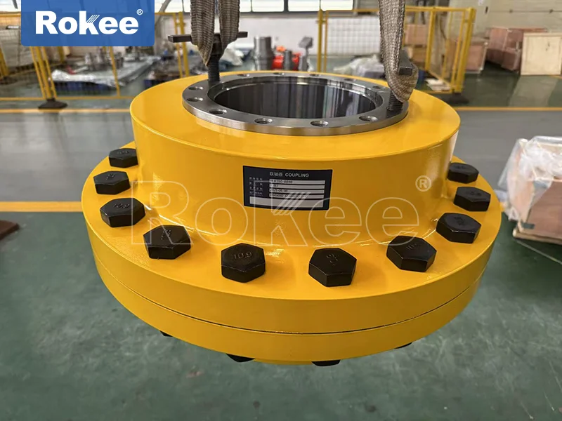
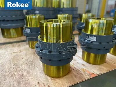
The flange coupling is composed of two flange plates (flange half coupling) connected by bolts, and has the following significant features:
Rigid connection design, capable of accurately transmitting motion and torque
Compact structure, small footprint
The installation has high requirements for neutrality
Suitable for high torque transmission scenarios
The main types and characteristics of flange couplings
Standard flange coupling
The most common type consists of two flanged shaft sleeves and a set of connecting bolts, suitable for most conventional transmission applications. Standard flange couplings can be subdivided into:
Flange type flange coupling
Flat flange coupling
Equipped with a flange coupling for the middle ringHeavy duty flange coupling
Specially designed for high torque applications, with thickened flanges and higher strength connecting bolts, commonly used for:
Heavy machinery
mining equipment
Large scale generator setPrecision flange coupling
Made with precision machining technology, it has extremely high coaxiality and balance, suitable for:
precision machine tool
High speed rotating equipment
measuring instrumentCorrosion resistant flange coupling
Using stainless steel or special coating treatment, suitable for:
chemical equipment
marine environment
Food processing machinery
When choosing a flange coupling, the following key parameters need to be considered:
Torque capacity: The maximum torque value that a coupling can transmit
Shaft diameter range: Suitable shaft diameter size range
Maximum speed: the highest rotational speed for safe operation
Allowable deviations: axial deviation, radial deviation, angular deviation.
Inertia moment: an important parameter that affects the dynamic performance of a system
Material characteristics: usually cast iron, cast steel, stainless steel or alloy steel
Selection Guide for Flange Couplings
Selection considerations
Transmission power and torque requirements
Shaft diameter size
Working environment (temperature, humidity, corrosiveness, etc.)
speed range
Installation space restrictions
Do you need insulation propertiesSelection steps
Determine the transmitted torque and speed
Consider operating condition factors (impact, vibration, etc.)
Choose appropriate size specifications
Check installation size compatibility
Confirm material suitability
Installation and maintenance of flange couplings
Installation key points
Ensure the accuracy of two axis alignment
Use appropriate installation tools
Tighten the bolts according to the specified torque value
Check the balance of the couplingroutine maintenance
Regularly check the tightening status of bolts
Monitor vibration and noise changes
Check the condition of the seals (if applicable)
Regular lubrication (required for certain types)Common faults and their solutions
Loose bolts: tighten or replace in a timely manner
Alignment deviation: recalibration
Flange deformation: replace damaged parts
Abnormal vibration: check balance and alignment
Flange couplings are widely used in:
Industrial machinery: pumps, fans, compressors, etc
Power generation equipment: steam turbine, generator, etc
Shipbuilding industry: propulsion systems, auxiliary machinery
Petrochemical equipment: various rotating mechanical connections
Metallurgical industry: rolling mills, conveying equipment
As a key component in mechanical transmission systems, the performance of flange couplings directly affects the operational efficiency and reliability of the entire system. The correct selection, installation, and maintenance of flange couplings are of great significance for extending equipment life and improving production efficiency.
In the complex world of mechanical engineering, numerous components work together to ensure the smooth and efficient operation of various machines and systems, and flange coupling is one of the most essential and widely used connecting parts. Serving as a critical link between two rotating shafts, flange coupling plays a pivotal role in transmitting power, torque, and motion from one shaft to another, while maintaining stability and alignment under different operating conditions. Unlike some specialized mechanical components that are limited to specific industries or applications, flange coupling boasts strong versatility, adapting to a wide range of working environments, from light-duty household machinery to heavy-duty industrial equipment. Its simple yet robust design, reliable performance, and diverse types make it an indispensable part of modern mechanical transmission systems.
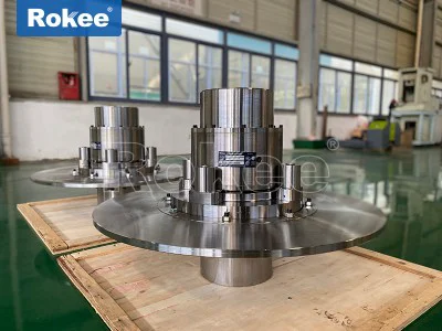
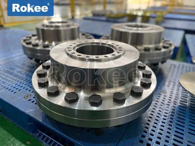
The structure of flange coupling is relatively intuitive but meticulously designed to ensure stable connection and efficient power transmission, with each component playing a unique and irreplaceable role. A typical flange coupling consists of several core components that work in coordination, and the specific structure may vary slightly according to different types and application requirements, but the basic composition remains consistent. The most fundamental components are two flange disks, which are circular plates usually made of high-strength materials to withstand the pressure, torque, and wear generated during operation. These flange disks are respectively mounted on the ends of the two shafts that need to be connected, and each flange disk is processed with a set of evenly distributed bolt holes around its circumference, which are used to fasten the two disks together. The number and size of the bolt holes are not arbitrary; they are precisely calculated based on the maximum torque that the coupling needs to transmit, ensuring that the bolts can bear the corresponding load without deformation or damage. In addition to the flange disks and bolts, nuts are used to lock the bolts, preventing loosening caused by vibration during operation, which is crucial for maintaining the stability of the connection. Some flange couplings, especially those used in fluid transmission systems or environments with high sealing requirements, are also equipped with gaskets or sealing rings between the two flange disks. These sealing components are usually made of elastic or corrosion-resistant materials, which not only prevent the leakage of fluids (such as oil, water, or gas) between the flanges but also help to buffer slight vibrations and compensate for minor alignment deviations, further improving the reliability of the coupling.
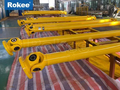
Another important structural feature of flange coupling is the connection method between the flange disk and the shaft. In most cases, a keyway is processed on the inner hole of the flange disk, and a corresponding key is installed between the flange disk and the shaft. This key connection ensures that the flange disk and the shaft rotate synchronously, avoiding relative sliding between them, thereby ensuring efficient torque transmission. The key is usually made of high-hardness metal materials to resist shear force and wear, and its size and shape are matched with the keyway to ensure a tight fit. For some special applications that require higher connection accuracy or larger torque transmission, the flange disk and the shaft may also adopt interference fit or shrink fit, which further enhances the stability and reliability of the connection, but this also increases the difficulty of installation and disassembly. In addition, some advanced flange coupling structures may be equipped with positioning pins or alignment sleeves, which are used to assist in the alignment of the two flange disks during installation, ensuring that the two shafts are coaxial, reducing the additional load caused by misalignment, and prolonging the service life of the coupling and the connected equipment.
The performance of flange coupling directly determines its applicability and reliability in different working environments, and it is mainly reflected in several key aspects, including torque transmission capacity, alignment accuracy, vibration resistance, corrosion resistance, temperature resistance, and maintainability. Torque transmission capacity is the most core performance index of flange coupling, as its primary function is to transmit torque between two shafts. The maximum torque that a flange coupling can transmit depends on various factors, such as the material of the flange disk and bolts, the size and number of bolts, the connection method between the flange disk and the shaft, and the structural design of the coupling. High-quality flange couplings can transmit large torques without deformation or damage, making them suitable for heavy-duty mechanical equipment such as mining machinery, metallurgical equipment, and marine propellers. On the contrary, light-duty flange couplings with smaller structural sizes are more suitable for small machinery with low torque requirements, such as household appliances and small pumps.
Alignment accuracy is another crucial performance index of flange coupling. During operation, the two shafts connected by the coupling must maintain a high degree of coaxiality; otherwise, additional forces will be generated, leading to increased vibration, accelerated wear of the coupling and bearing, and even damage to the equipment in severe cases. Therefore, flange coupling is designed to have a certain alignment capacity, which can compensate for minor radial, axial, or angular deviations between the two shafts. The alignment capacity varies according to the type of flange coupling: rigid flange couplings have almost no alignment capacity and require strict coaxiality during installation, while flexible flange couplings can compensate for certain deviations through elastic components, reducing the requirements for installation accuracy. Vibration resistance is also an important performance of flange coupling, as mechanical equipment will inevitably generate vibration during operation. If the coupling cannot effectively buffer vibration, the vibration will be transmitted between the shafts, affecting the stability of the entire system and shortening the service life of the components. Some flange couplings are equipped with elastic components such as rubber pads or springs, which can absorb and buffer vibration, reduce noise, and protect the connected equipment.
Corrosion resistance and temperature resistance are performance indexes that determine the applicability of flange coupling in special environments. In industries such as chemical engineering, petroleum, and marine engineering, the coupling may be exposed to corrosive media such as acid, alkali, salt, or seawater, so it is necessary to use flange couplings made of corrosion-resistant materials, such as stainless steel, alloy steel, or non-metallic materials with anti-corrosion coatings. These materials can effectively resist the erosion of corrosive media, ensuring the normal operation of the coupling in harsh environments. Temperature resistance is also crucial for flange couplings used in high-temperature or low-temperature environments, such as boiler equipment, steam turbines, or refrigeration systems. The materials and sealing components of the coupling must be able to withstand extreme temperatures without losing their performance; otherwise, the coupling may deform, crack, or the sealing components may fail, leading to system failure. Maintainability is another practical performance index of flange coupling. A well-designed flange coupling should be easy to install, disassemble, and maintain, reducing the downtime of the equipment and the maintenance cost. For example, flange couplings with split flange disks can be disassembled without moving the connected shafts, which greatly improves the maintenance efficiency.
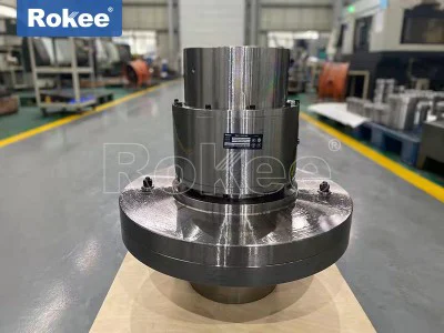
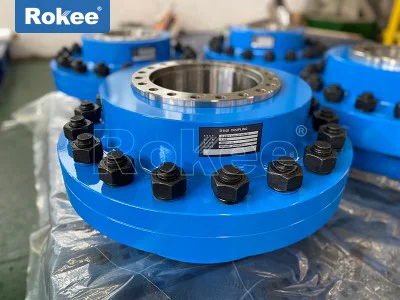
Based on structural characteristics, performance differences, and application requirements, flange coupling can be divided into several main types, each with its own unique characteristics and applicable scenarios. The most common types include rigid flange coupling, flexible flange coupling, and marine flange coupling, and each type can be further subdivided into different subtypes according to specific structural designs. Rigid flange coupling is the simplest and most widely used type, characterized by a rigid structure without any elastic components. It consists of two flange disks and a set of bolts, and the two flange disks are directly fastened together, making the two shafts form a rigid connection. Due to its rigid structure, this type of coupling has high torque transmission capacity and high connection accuracy, but it has almost no ability to compensate for shaft deviations or buffer vibration. Therefore, it is suitable for occasions where the two shafts have high coaxiality, stable load, and no significant vibration, such as precision machine tools, electrical machinery, and transmission shafts of general machinery. Rigid flange coupling can be further divided into unprotected flange coupling and protected flange coupling: the bolts and nuts of the unprotected type are exposed outside, which is simple in structure and low in cost, but there is a potential safety hazard of accidental contact with rotating components; the protected type is equipped with a protective cover around the bolts and nuts, which can prevent dust, debris, and other contaminants from entering the coupling, and also avoid accidental contact, improving safety and reliability.
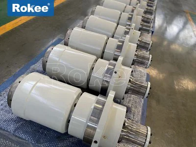
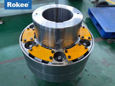
Flexible flange coupling is a type of coupling with elastic components, which is designed to solve the problems of shaft misalignment, vibration, and impact in mechanical transmission systems. Compared with rigid flange coupling, flexible flange coupling adds one or more elastic components between the two flange disks, such as rubber pads, polyurethane blocks, springs, or metal diaphragms. These elastic components can not only transmit torque but also compensate for minor radial, axial, or angular deviations between the two shafts, absorb vibration, and buffer impact, thereby protecting the connected equipment and reducing noise. The performance of flexible flange coupling mainly depends on the material and structure of the elastic components: elastic components made of rubber or polyurethane have good vibration absorption and buffering performance but poor high-temperature resistance and aging resistance, making them suitable for general temperature and light to medium load occasions; elastic components made of metal diaphragms have high temperature resistance, high pressure resistance, and long service life, making them suitable for high-temperature, high-speed, and heavy-duty occasions, such as aerospace, automotive, and steam turbine equipment. Common subtypes of flexible flange coupling include elastomeric flange coupling, diaphragm flange coupling, and grid flange coupling, each with its own advantages and applicable scenarios.
Marine flange coupling is a specialized type of flange coupling designed for marine environments, which has the characteristics of high corrosion resistance, high torque transmission capacity, and good sealing performance. Marine equipment, such as ship propellers, marine engines, and marine pumps, operates in harsh environments with high humidity, high salt content, and large load changes, so the requirements for flange coupling are extremely strict. Marine flange coupling is usually made of corrosion-resistant materials such as stainless steel or alloy steel, and its surface is treated with anti-corrosion coatings to resist the erosion of seawater and humid air. The sealing structure of marine flange coupling is also specially designed, using high-performance sealing rings or gaskets to prevent seawater from entering the coupling, ensuring the normal operation of the coupling in marine environments. In addition, marine flange coupling has high torque transmission capacity to meet the power transmission needs of marine engines and propellers, and it also has a certain vibration absorption capacity to adapt to the vibration generated by marine equipment during navigation. Due to its specialized design, marine flange coupling is not only used in ships but also in other marine-related equipment, such as offshore oil platforms and marine wind turbines.
The wide range of applications of flange coupling is closely related to its diverse types, reliable performance, and simple structure, covering almost all fields of mechanical engineering, from daily life to industrial production, from light-duty machinery to heavy-duty equipment. In the field of general machinery, flange coupling is widely used in pumps, fans, compressors, conveyors, and other equipment, playing a role in connecting the motor and the working machine, transmitting power and torque, ensuring the normal operation of the equipment. For example, in water supply and drainage systems, flange coupling connects the motor and the water pump, transmitting the torque of the motor to the pump impeller, enabling the pump to transport water; in ventilation systems, flange coupling connects the motor and the fan, driving the fan blades to rotate, realizing ventilation and air exchange.
In the field of heavy industry, flange coupling plays an even more important role, as heavy-duty mechanical equipment requires stable and efficient torque transmission. In mining machinery, such as coal mining machines, belt conveyors, and crushers, flange coupling is used to connect the motor, reducer, and working mechanism, transmitting large torques to drive the equipment to work under harsh conditions such as heavy load, high vibration, and high dust. In metallurgical equipment, such as blast furnaces, rolling mills, and continuous casting machines, flange coupling is used in various transmission systems, withstanding high temperature, high pressure, and large torque, ensuring the smooth operation of the metallurgical production line. In construction machinery, such as excavators, cranes, and loaders, flange coupling is used to connect the engine, hydraulic pump, and other components, transmitting power to the working mechanism, enabling the machinery to complete various construction operations.
The aerospace and automotive industries also have high requirements for flange coupling, which need to have high precision, high reliability, high temperature resistance, and light weight. In aerospace equipment, such as aircraft engines, helicopters, and satellites, flange coupling is used in the transmission system of the engine and other components, transmitting power under high-speed, high-temperature, and high-pressure conditions, requiring extremely high performance and reliability to ensure flight safety. In the automotive industry, flange coupling is used in the transmission system, drive axle, and other parts of the automobile, transmitting torque from the engine to the wheels, withstanding frequent load changes and vibration, and requiring good durability and vibration absorption performance. With the development of electric vehicles, the requirements for flange coupling are becoming higher and higher, requiring it to be more efficient, energy-saving, and quiet.
In the field of petrochemical and chemical engineering, flange coupling is widely used in pumps, compressors, reactors, and other equipment, which need to have good corrosion resistance and sealing performance to adapt to the harsh environment of corrosive media and high pressure. For example, in oil refineries, flange coupling connects the motor and the oil pump, transmitting power to transport crude oil, gasoline, diesel, and other media; in chemical plants, flange coupling is used in the transmission system of chemical pumps and reactors, withstanding the erosion of acid, alkali, and other corrosive media, ensuring the normal operation of chemical production.
Marine engineering is another important application field of flange coupling, as mentioned earlier, marine equipment such as ship propellers, marine engines, and marine pumps all need to use marine flange coupling to ensure stable power transmission in marine environments. In addition, offshore oil platforms, marine wind turbines, and other marine-related equipment also widely use flange coupling, which needs to have high corrosion resistance, high wind resistance, and high reliability to adapt to the harsh marine environment.
In addition to the above fields, flange coupling is also used in many other fields, such as medical equipment, food processing machinery, and household appliances. In medical equipment, such as medical pumps, diagnostic equipment, and surgical instruments, flange coupling is used in the transmission system, requiring high precision, low noise, and high reliability to ensure the accuracy and safety of medical operations. In food processing machinery, such as food conveyors, mixers, and packaging machines, flange coupling is used to connect the motor and the working mechanism, requiring clean, non-toxic, and easy to clean to meet the hygiene requirements of food processing. In household appliances, such as washing machines, refrigerators, and air conditioners, flange coupling is used in the transmission system of motors and compressors, requiring small size, light weight, low noise, and long service life to improve the performance and service life of household appliances.
With the continuous development of mechanical engineering technology, the design and manufacturing level of flange coupling is also constantly improving. New materials, new processes, and new structures are constantly applied to flange coupling, making it more efficient, reliable, and versatile. For example, the application of composite materials makes flange coupling lighter and more corrosion-resistant; the adoption of precision machining technology improves the structural accuracy and performance stability of flange coupling; the design of intelligent flange coupling with monitoring functions can realize real-time monitoring of the operating status of the coupling, timely find potential faults, and improve the reliability and safety of the system.
In conclusion, flange coupling is an indispensable connecting component in modern mechanical transmission systems, whose structure, performance, types, and applications are closely related to the smooth operation of various mechanical equipment. Its simple yet robust structure ensures stable connection and efficient power transmission; its excellent performance enables it to adapt to different working environments and load requirements; its diverse types meet the diverse needs of various industries and applications; and its wide range of applications covers almost all fields of mechanical engineering. Understanding the structure, performance, types, and applications of flange coupling is of great significance for the selection, installation, use, and maintenance of flange coupling in practical engineering, which can not only improve the efficiency and reliability of mechanical equipment but also reduce maintenance costs and extend the service life of equipment. As mechanical engineering technology continues to advance, flange coupling will surely play a more important role in future industrial production and social life, contributing more to the development of human society.