Universal Joint Coupling For Lifting Equipment

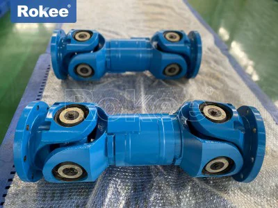
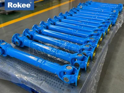
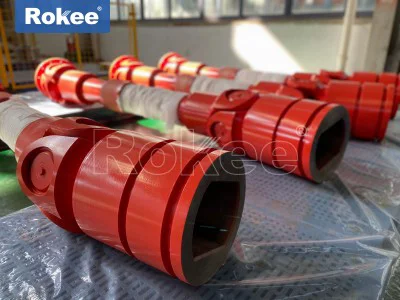
Lifting equipment operates in constantly changing mechanical environments where structural deflection, dynamic loading, and minor positional shifts can pull drive shafts out of perfect alignment, creating serious risks for rigid transmission components that cannot tolerate misalignment. The universal joint coupling stands out as a specialized power transmission component built specifically to resolve this challenge for lifting machinery, transferring rotational torque and motion between two non-collinear shafts while accommodating angular, axial and radial offsets that emerge during lifting cycles. Unlike rigid couplings that demand precise coaxial installation and may suffer sudden fracture under misaligned load, the universal joint coupling relies on articulated mechanical joints to maintain continuous power transfer even when the driving and driven shafts form an included angle. In lifting systems, loads fluctuate dramatically as heavy objects are hoisted, lowered, moved horizontally or rotated, and these variable forces bend support frames and shift bearing positions. Such dynamic movement makes perfect shaft alignment almost impossible to sustain throughout operation, and without a compensating coupling, repeated stress accumulates on gearboxes, motor bearings and shaft ends, accelerating fatigue and triggering unexpected shutdowns. The universal joint coupling absorbs these positional deviations internally, isolating upstream and downstream components from harmful bending loads and preserving the integrity of the whole drive train. Its fundamental mechanical layout combines yokes mounted to each shaft end and a central cross-shaped spider fitted with bearing assemblies, forming hinged connections that allow free pivoting movement across two perpendicular planes. This simple yet robust mechanical arrangement enables lifting equipment designers to build compact transmission layouts where drive units are offset from winch drums or slewing mechanisms, without sacrificing torque capacity or operational stability.
The working principle of universal couplings for lifting equipment depends on spatial kinematics of the cross spider and yoke assembly, converting fixed-axis rotation of the input shaft into compound pivoting motion before delivering torque to the output shaft. When the driving yoke rotates, force transfers to the cross spider through precision bearings, and the spider then drives the second yoke and the connected driven shaft. Each bearing fitted on the four arms of the cross spider allows independent swinging motion within the yoke housing, creating room for angular deflection between shafts. A single universal joint generates fluctuation in angular velocity across one full rotation when an operating angle exists between shafts, which introduces pulsating torque that can create vibration under heavy lifting loads. To mitigate this characteristic, lifting equipment most commonly uses paired universal joints arranged in sequence, which cancels out velocity variation and delivers nearly constant rotational speed to the load end. This dual-joint configuration is widely adopted in hoist winch drives and crane slewing assemblies, where steady torque delivery is critical to prevent load jerking during lifting and lowering operations. The sliding spline section integrated into many universal joint coupling assemblies adds another layer of compensation, absorbing axial displacement caused by thermal expansion of metal structures and temporary stretching under heavy load. As lifting equipment raises and lowers massive weights, frame members stretch and contract, and the spline sleeve slides along the spline shaft to adjust overall coupling length, avoiding compressive or tensile forces that would otherwise push or pull connected drive components. All moving contact surfaces inside the coupling are engineered to sustain repeated impact and cyclic loading inherent to lifting tasks, where torque spikes occur the instant a suspended load lifts off supporting surfaces.
Material selection for universal joint couplings in lifting applications prioritizes high strength, fatigue resistance and wear tolerance, as these components repeatedly endure shock torque, vibration and abrasive environmental conditions. Forged alloy steel serves as the primary material for cross spiders, yokes and flanged connection ends, offering exceptional tensile strength and resistance to crack propagation under cyclic heavy loads. The forging process refines internal grain structure of the metal, removing voids and inclusions that could become failure initiation points under fluctuating lifting torque, a critical advantage over cast alternatives that may contain hidden porosity. Bearing races and rolling elements are manufactured from hardened steel to withstand continuous sliding and pivoting friction inside the joint, while surface treatment processes improve hardness and corrosion resistance. Lifting equipment often works in environments exposed to dust, moisture and temperature swings, and protective surface coatings slow rust formation and reduce abrasive particle wear on joint surfaces. Material choices balance hardness and toughness; overly brittle materials may crack under sudden load spikes when a hoist picks up a heavy item, while softer materials deform quickly and develop excessive backlash after limited operating hours. Designers also consider thermal performance, as continuous operation generates friction heat inside bearing assemblies, and selected materials retain mechanical properties across wide temperature ranges. Every material choice directly impacts service life and safety because a coupling failure during lifting can lead to loss of load control. Engineers carefully match material grades to expected peak torque, cycle frequency and environmental exposure of each lifting application, ensuring the finished coupling maintains structural integrity through millions of lifting cycles without developing hidden structural damage.
Universal joint couplings serve multiple functional positions across different categories of lifting machinery, with each installation presenting unique load and motion requirements. They are frequently installed in winch drive systems, connecting electric or hydraulic drive motors to the hoist drum gearbox, where frame deflection during load lifting creates angular offset between motor and gearbox shafts. Mobile lifting machinery also uses these couplings within slewing mechanisms, transmitting power to rotate the boom and suspended load, a motion that constantly shifts relative positions between the power source and slewing gear set. For gantry lifting frames and overhead travelling lifting systems, universal joint couplings connect distributed drive units that run along support beams, compensating for minor structural distortion when the trolley moves across the span and carries heavy loads. Some lifting platforms and material handling elevators adopt universal joint couplings to synchronize multiple drive shafts, ensuring coordinated movement between separate lifting points even when small positional differences develop between support structures. In each application, the coupling’s core role remains consistent: transmit high torque while accommodating dynamic misalignment, protecting expensive drive components from bending stress. Installation layouts vary widely based on available space, required deflection angle and peak torque demand. Compact short-coupling designs fit tight spaces where only limited axial length is available, while longer versions with extended spline sections suit systems requiring larger axial compensation. Regardless of layout, the coupling must be positioned so operating angles stay within the designed working range during normal lifting, lowering and travelling movements, preventing excessive internal friction and accelerated wear on bearing components.
The key operational advantages of universal joint couplings make them uniquely suited for heavy-duty lifting environments, setting them apart from rigid and elastic coupling alternatives. First, their outstanding angular compensation capability handles far larger shaft deflection angles than most flexible couplings, allowing lifting equipment to keep operating safely even when structural deformation shifts shaft alignment under load. Second, these couplings deliver high torque transmission capacity combined with good mechanical efficiency, minimizing power loss between drive and load; this efficiency reduces energy consumption and limits heat buildup during extended lifting operations. Their modular construction simplifies assembly and disassembly during maintenance, since individual joint sections or bearing sets can be accessed without fully removing adjacent drive equipment. Universal joint couplings also tolerate shock torque that commonly appears in lifting equipment at load pickup, when static friction is overcome and the suspended mass suddenly transfers force into the drive train. Unlike elastomeric couplings that can tear or degrade under repeated heavy shock and exposure to harsh contaminants, metal universal joint structures maintain their load carrying capacity over long periods, provided lubrication is properly maintained. Another practical benefit is their ability to combine angular, radial and axial compensation in a single assembly, removing the need for multiple separate compensating components within the drive line and simplifying the overall mechanical layout of lifting machinery. All these advantages translate into more reliable lifting operation, reduced downtime for alignment corrections, and lower risk of secondary damage to motors, gearboxes and shafts caused by misalignment forces.
Even with robust performance characteristics, universal joint couplings for lifting equipment carry inherent limitations that must be understood and managed in system design. The velocity fluctuation from a single universal joint remains a fundamental mechanical trait, which is why single joints are rarely used alone in load-critical lifting drives; paired joints become necessary to smooth out rotational output and prevent load oscillation. Internal bearings and cross spider contact surfaces experience sliding and rolling friction every time the joint pivots under load, which generates wear over time. As bearing surfaces wear, mechanical backlash increases, and this play can create jerking motion when lifting direction reverses, introducing dynamic shock into the suspended load. Operating at extreme deflection angles accelerates wear significantly, raising friction and heat generation inside the joint, and prolonged use beyond recommended angles can lead to premature bearing seizure or spider fracture. Universal joint couplings also require continuous lubrication to reduce metal-to-metal contact inside bearing races. If lubricant becomes contaminated with dust, water or metal debris from wear, abrasion speeds up rapidly. Unlike some elastomeric couplings, universal joint assemblies offer limited damping for high-frequency vibration, so additional vibration control measures may be required in certain lifting drive systems. Backlash can never be fully eliminated from the hinged joint structure, which makes them less ideal for applications demanding ultra-precise positioning with zero play. When designing lifting machinery, engineers evaluate these drawbacks against system requirements, limiting operating angles, adding proper lubrication ports, selecting appropriate bearing designs and arranging dual-joint configurations to counteract velocity variation and minimize the impact of these inherent limitations.
Lubrication and routine maintenance are central to preserving the performance and service life of universal joint couplings fitted on lifting equipment, as these components rely on a stable lubricating film to protect moving metal contact surfaces. Lubricant fills the small clearances between bearing rollers, cross spider journals and yoke bores, reducing friction and carrying away heat produced by pivoting motion under heavy torque. Without adequate lubrication, direct metal contact creates scoring, pitting and rapid bearing wear, which can progress unnoticed until sudden joint failure during a lifting operation. Grease is the most common lubricant choice for lifting universal joint couplings because it stays in place within enclosed bearing cavities, resists washout from moisture and forms a protective barrier against dust and grit present in industrial lifting environments. Maintenance procedures involve periodic grease injection through built-in grease fittings, while old degraded lubricant is purged to remove accumulated metal particles and contaminants. Inspection tasks include checking for grease leakage at bearing seals, which indicates damaged sealing components that allow dirt ingress and lubricant loss. Technicians also assess joint backlash by manually rotating the coupling under unloaded conditions, measuring free play to determine whether internal bearing components have worn beyond acceptable limits. Visual inspection looks for surface cracks, corrosion, deformed yoke flanges and loose fasteners connecting coupling sections to drive shafts. Maintenance schedules are adjusted according to operating frequency; couplings used for continuous heavy lifting require more frequent checks than those operating intermittently. Proper record keeping of lubrication service and wear measurements helps track component degradation over time, enabling planned replacement before failure occurs and avoiding unplanned downtime or hazardous lifting incidents.
Installation and alignment practices for universal joint couplings in lifting equipment follow careful procedures to maximize component lifespan and avoid introducing unnecessary operating stress. While these couplings are engineered to accommodate misalignment, they are not designed to compensate for gross installation errors, and excessive initial offset imposes continuous overload on internal bearings. Before mounting, technicians inspect all coupling components for manufacturing defects, damage from handling, and cleanliness, ensuring no foreign particles enter bearing assemblies during assembly. The flanged ends are attached securely to driving and driven shafts with evenly tensioned fasteners, using controlled tightening sequences to prevent flange distortion that could create uneven load distribution across bolt circles. When installing dual universal joint assemblies, the phase position of the two yokes must be set correctly to counteract angular velocity fluctuation; improper phasing will amplify vibration and torque pulsation during rotation, causing load bounce and accelerated wear. After fastening, the equipment is moved through its full working range to verify the actual operating angle of the coupling under loaded and unloaded states, confirming that deflection stays within the intended range across all lifting, travelling and slewing positions. Axial clearance of the spline section is also checked to ensure enough room for thermal expansion and structural displacement, while avoiding excessive slack that generates impact loads during direction changes. Once installation completes, low-load test runs are performed to listen for abnormal noise, check for vibration and confirm no binding occurs as the coupling pivots through its motion range. Correct installation reduces premature wear, ensures the coupling performs its intended compensation function, and maintains the safety margin required for lifting equipment handling suspended heavy loads.
Failure analysis of universal joint couplings in lifting systems reveals recurring root causes that help refine equipment design, operation and maintenance practices. A large share of coupling failures stems from insufficient or degraded lubrication, which allows bearing seizure and spider journal wear. Contaminants entering damaged seals scratch bearing surfaces and create abrasive wear cycles that progressively remove material from critical load-bearing contact points. Another common failure mode is overloading beyond the torque capacity of the coupling, often from sudden dynamic shock when loads swing or catch on obstructions during lifting. Repeated overload creates fatigue cracks starting at stress concentration points on the cross spider or yoke shoulders, and these cracks grow slowly over many lifting cycles until the component fractures without advance warning. Excessive operating angle, frequently caused by structural settlement or shifting of equipment supports, increases internal friction and bending stress, accelerating fatigue failure. Improper assembly, including misaligned yoke phasing, uneven bolt tension or incorrect spline engagement, introduces vibration and cyclic stress that shorten service life. Corrosion also contributes to degradation in humid or chemically active working environments, pitting metal surfaces and creating crack initiation sites. When a coupling fault is identified, inspection includes checking adjacent drive components, because coupling damage may be a symptom of other underlying issues such as gearbox damage, loose mountings or structural frame distortion. Learning from these failure events helps designers select appropriately sized couplings, operators avoid abusive load handling, and maintenance teams focus inspection on high-risk areas, strengthening overall reliability of lifting transmission systems.
The ongoing evolution of universal joint coupling design continues to enhance suitability and safety for modern lifting equipment, responding to demands for heavier load capacity, longer service intervals and improved environmental resistance. Advanced manufacturing techniques refine the precision of cross spider and bearing geometry, distributing contact stress more evenly and reducing local pressure peaks during torque transfer. Improved sealing structures better block dust, moisture and chemical contaminants, extending lubricant service life and lowering maintenance frequency for couplings working in harsh industrial lifting sites. Optimized spline surface treatments reduce friction and wear at sliding interfaces, preserving axial compensation performance through many operating cycles. Some updated designs integrate structural features that limit maximum deflection angle mechanically, preventing operators from pushing the coupling beyond safe working limits during equipment setup. Design workflows increasingly use dynamic simulation tools to model torque fluctuation, structural deformation and wear accumulation across complete lifting cycles, allowing engineers to tailor coupling dimensions and material specifications for unique lifting applications rather than relying solely on static torque calculations. These developments do not change the fundamental mechanical principle of the universal joint coupling, but they improve consistency, robustness and predictability of performance under variable lifting loads. As lifting machinery grows more capable of handling larger and more complex suspended loads, universal joint couplings remain a foundational transmission solution. Ongoing refinement ensures this mature mechanical component continues to meet evolving operational requirements while protecting lifting drive trains from the unavoidable misalignment and dynamic loading that define heavy lifting work.