Installation Error And Adjustment Method Of Cardan Coupling In PU Sandwich Panel Line
The normal and stable operation of mechanical transmission components is the core foundation to ensure the continuous production efficiency and product processing quality of PU sandwich panel production lines. As a key universal transmission component responsible for connecting driving and driven equipment, transmitting rotational torque, and compensating for slight shaft position deviations in the production line, the cardan coupling undertakes the important task of linking multiple core process sections of the PU sandwich panel line, including raw material feeding, continuous panel pressing, foaming compounding, fixed-length cutting and finished product conveying. The production characteristics of PU sandwich panel lines determine that the transmission system needs to maintain long-term continuous operation under stable torque output and low vibration conditions, and any minor installation deviation or assembly irregularity of the cardan coupling will gradually evolve into abnormal transmission vibration, torque transmission attenuation, accelerated wear of matching parts, and even intermittent shutdown failures in the long-term cyclic production process. These adverse problems will not only directly reduce the dimensional accuracy and surface flatness of the produced PU sandwich panels, leading to unstable bonding effect between the core material and the surface plate, but also increase the frequent replacement frequency of mechanical parts and the daily maintenance workload of the production line, bringing unnecessary production delays and operational losses to the entire production and processing process. In the actual on-site installation and daily commissioning work of PU sandwich panel production lines, most equipment operation and maintenance personnel often focus on the debugging of foaming formula parameters, pressing roller pressure control and cutting precision calibration, and easily ignore the fine installation standard control and accurate alignment adjustment of the cardan coupling. This habitual neglect leads to various potential installation errors remaining hidden in the transmission system in the initial stage of equipment operation, and these hidden dangers will continuously amplify with the increase of production operation time and the accumulation of mechanical fatigue, eventually triggering a series of mechanical failures that affect the normal progress of production. Therefore, fully clarifying the common types of installation errors of cardan couplings in PU sandwich panel production lines, analyzing the root causes of each error and the adverse impact mechanism on production operation and equipment service life, and mastering scientific, standardized and targeted installation adjustment and calibration methods are essential basic work to maintain the long-term stable and efficient operation of the entire PU sandwich panel production line, extend the service cycle of transmission components, reduce equipment failure rate and comprehensive operation cost, and ensure the consistent and qualified quality of finished sandwich panel products.
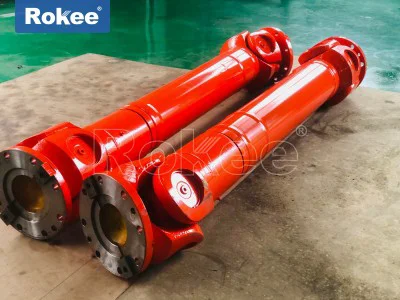
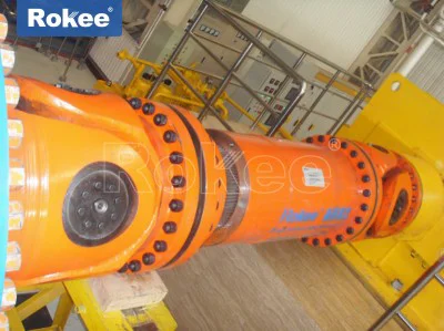
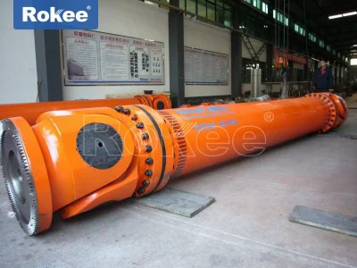
The structural operation characteristics of cardan couplings determine their high sensitivity to installation accuracy and assembly standardization in the application scenario of PU sandwich panel production lines. Different from ordinary rigid transmission couplings, cardan couplings rely on the special hinge connection structure of universal joint forks and cross shaft components to realize torque transmission between two shafts with a certain degree of angular, axial and radial displacement compensation capability. This flexible compensation performance makes cardan couplings widely applicable to the transmission connection of various mechanical equipment with slight installation position deviations and small operational vibration displacement, especially suitable for the complex transmission working conditions of PU sandwich panel production lines where multiple transmission shafts are arranged in a staggered manner and the equipment will generate slight mechanical shaking during continuous pressing and foaming production. However, this inherent flexible structural feature also means that the cardan coupling cannot offset excessive installation misalignment and non-standard assembly problems through its own compensation function. Once the installation error exceeds the allowable deviation range specified by the transmission design, the universal joint forks, cross shaft bearings, spline pairs and other core load-bearing and transmission parts inside the coupling will bear additional alternating impact loads that are not designed in the working process. The PU sandwich panel production line needs to run continuously for a long time without frequent shutdowns in the actual production process, and the transmission system is always in a cyclic rotating working state with stable load. The additional alternating load generated by installation errors will act on the key parts of the cardan coupling for a long time and repeatedly, resulting in uneven stress distribution of each component, accelerated friction and wear of contact surfaces, early fatigue aging of metal structures, and even deformation and fracture of key transmission parts in severe cases. In the actual production and operation process of many PU sandwich panel factories, most of the sudden transmission jitter, equipment abnormal noise, panel pressing unevenness and unplanned shutdown maintenance problems are indirectly or directly caused by uncorrected installation errors of cardan couplings. Many operation and maintenance personnel only carry out simple replacement and temporary troubleshooting after the failure occurs, but do not trace back to the fundamental installation error problems and carry out standardized adjustment and calibration, resulting in repeated failures of the same transmission part, forming a vicious cycle of frequent maintenance and unstable production, which seriously restricts the production capacity and economic benefit improvement of the PU sandwich panel production line.
Among all the installation problems of cardan couplings in PU sandwich panel production lines, angular misalignment installation error is the most common and most influential type of hidden danger in actual operation, and it is also the installation error type that is most likely to be ignored in the initial equipment assembly and later coupling replacement and reinstallation process. Angular misalignment mainly refers to the phenomenon that the central axis of the driving shaft connected to the cardan coupling and the central axis of the driven shaft on the production line are not kept parallel and concentric as required by the design, and there is an excessive included angle deviating from the standard installation position. In the design specification of the transmission system of PU sandwich panel production lines, the allowable angular deviation of the two connected shafts of the cardan coupling is controlled within a very small reasonable range, because the torque transmission stability of the cardan coupling is closely related to the matching angle of the universal joint forks at both ends. When the installation angular deviation is within the standard range, the coupling can rely on its own structural characteristics to realize smooth and uniform torque transmission, and the stress of each internal component is balanced and within the designed bearing range. Once the installation operation causes the angular misalignment angle to exceed the design allowable value, the periodic speed fluctuation will occur in the torque transmission process of the cardan coupling. This speed fluctuation will not only cause obvious vibration and resonance of the transmission shaft during rotation, but also lead to periodic impact on the cross shaft and bearing components inside the coupling in each rotation cycle. For the PU sandwich panel line with high requirements for transmission stability, this vibration and impact will be directly transmitted to the pressing roller group and the conveying platform of the production line, resulting in slight jitter during the conveying and pressing process of the PU sandwich panel raw materials and semi-finished products. The direct consequence of this jitter is the uneven thickness of the foamed sandwich core material, inconsistent bonding gap between the upper and lower surface plates and the core material, and local depressions or bulges on the surface of the finished panel, which seriously reduces the overall quality and appearance flatness of the product. The main root causes of angular misalignment installation errors in actual installation operation are concentrated in three aspects. First, in the initial installation and positioning stage of the production line equipment, the foundation fixing bolts of the driving motor, reducer and transmission frame are not locked firmly after preliminary positioning, and the slight displacement of the equipment base occurs during the subsequent concrete curing and equipment preliminary debugging process, resulting in the deviation of the shaft body installation angle connected with the cardan coupling. Second, when the cardan coupling is replaced and maintained regularly in the later stage, the maintenance personnel only focus on the quick disassembly and installation of the coupling bolts, and do not use professional measuring tools to calibrate the parallelism and angle of the driving and driven shafts after replacement, and directly put the equipment into operation by experience, resulting in cumulative angular deviation after repeated disassembly and assembly. Third, after the long-term operation of the production line, the equipment base will produce slight settlement and mechanical deformation due to long-term load pressure and vibration impact, and the position and angle of the transmission shaft connected to the coupling will change accordingly, and the uncorrected angle deviation will gradually increase over time.
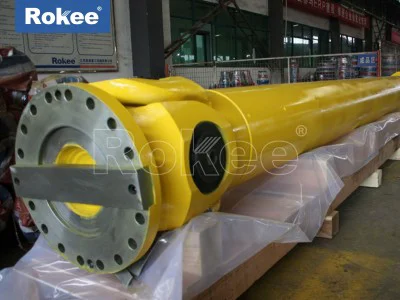
Axial installation deviation error is also a typical common installation problem of cardan couplings in PU sandwich panel production lines, which mainly refers to the excessive axial spacing deviation between the driving shaft end and the driven shaft end connected by the cardan coupling, and the telescopic spline pair inside the coupling cannot work within the normal design telescopic stroke range. The cardan coupling used in PU sandwich panel production lines is generally equipped with a telescopic spline structure, which is designed to adapt to the slight axial displacement of the transmission shaft caused by thermal expansion and cold contraction during equipment operation and slight position movement during mechanical vibration. The normal axial installation position requires that the spline pair of the coupling is in the middle position of the telescopic stroke when the equipment is in a static shutdown state, so that it can have enough telescopic allowance to buffer the axial displacement generated during equipment operation, avoiding the spline pair being stuck due to excessive extension or compression. In the actual installation process, many installation and maintenance personnel often have two extreme operation errors leading to axial deviation. One is that the installation spacing of the two shafts is too small, resulting in the spline pair of the cardan coupling being in a compressed state for a long time after installation, with no reserved telescopic allowance. When the equipment runs and generates thermal expansion of the shaft body and mechanical vibration displacement, the spline pair cannot be compressed further, resulting in excessive axial pressure on the coupling, rigid friction between the spline shaft and the spline sleeve, and rapid wear of the spline tooth surface. The other is that the installation spacing of the two shafts is too large, resulting in the spline pair of the coupling being excessively extended after installation, the meshing length of the spline teeth is insufficient, and the effective torque transmission area is reduced. In the high-load transmission process of the PU sandwich panel pressing section, the insufficient meshing length of the spline teeth will cause local stress concentration of the spline pair, tooth surface abrasion and even tooth breakage failure in serious cases. The adverse effects of axial installation deviation on the production line are relatively hidden in the early stage, and there is no obvious abnormal vibration and noise in the initial operation stage of the equipment. With the extension of operation time, the wear of the spline pair gradually intensifies, resulting in axial runout of the transmission shaft, unstable torque transmission, and then affecting the synchronous operation coordination of each process section of the PU sandwich panel production line, leading to inconsistent conveying speed of the panel, foaming material filling deviation, and finally affecting the overall structural strength and dimensional stability of the finished sandwich panel.
Radial installation runout error and non-standard phasing assembly error are two auxiliary installation error types that cannot be ignored, and their combined effect with angular and axial deviations will further aggravate the operation failure risk of the cardan coupling. Radial runout error means that the driving shaft and driven shaft connected by the coupling have different centers in the radial direction, and there is obvious radial eccentricity during the rotation process. This error is mainly caused by the inaccurate positioning of the flange connection surface during coupling installation, the unclean fitting surface with sundries and rust, and the unbalanced locking force of the connecting bolts. When radial runout occurs, the coupling will generate periodic centrifugal force during rotation, causing the transmission shaft to vibrate radially, accelerating the wear of coupling bearings and transmission shaft bearings, and shortening the service life of all rotating parts in the transmission system. Phasing assembly error refers to the misalignment of the phase marks of the universal joint forks at both ends of the cardan coupling during installation. The design of the cardan coupling requires that the fork bodies of the two universal joints must maintain a specific phase angle position to ensure the constant speed and stability of torque transmission. If the phase marks are not aligned during installation and the assembly is carried out in a random staggered state, the coupling will produce irregular torque fluctuation and rotational speed jitter in the rotation process. In the continuous production process of PU sandwich panels, this irregular jitter will lead to unstable operation of the pressing roller and cutting device, resulting in inaccurate fixed-length cutting of the sandwich panel and uneven pressing density of the core material, reducing the yield of qualified products. In addition, some indirect installation auxiliary errors such as unqualified thread treatment of coupling connecting bolts and irregular lubrication filling during installation will also indirectly affect the installation and operation effect of the cardan coupling. For example, the bolt threads are not cleaned and polished before locking, resulting in insufficient bolt fastening tightness and easy loosening during operation; the lubricating grease is not filled according to the standard during installation, resulting in dry friction of the coupling hinge parts in the initial operation stage and rapid early wear.
Aiming at the above various common installation errors of cardan couplings in PU sandwich panel production lines, targeted standardized adjustment and calibration methods must be adopted in strict accordance with equipment transmission design requirements and on-site production actual conditions to eliminate deviation hidden dangers and ensure that the coupling installation state meets the normal operation standards. The whole adjustment and calibration work needs to be carried out in the state of equipment power-off and shutdown to ensure construction safety and avoid mechanical injury accidents during adjustment operation. Before all adjustment work starts, the first basic step is to thoroughly clean all connection parts of the cardan coupling and the matching flange surfaces of the driving and driven shafts, remove all dirt, rust, welding slag and residual sundries on the fitting surfaces, ensure that the connection surfaces are flat and clean without any protrusions and depressions, and prepare professional measuring tools such as dial indicators, straightedges and level gauges to provide accurate data support for subsequent alignment and deviation measurement. For the adjustment of angular misalignment error, it is necessary to first fix the position of the main driving equipment such as the driving motor and reducer, take the central axis of the driving shaft as the benchmark, use a level gauge and straightedge to measure the parallelism and angle deviation between the driven shaft and the driving shaft section by section, record all deviation data in detail, and adjust the height and horizontal position of the driven equipment base by adding or removing adjusting gaskets at the equipment base fixing bolts. During the adjustment process, fine adjustment must be carried out multiple times with small deviations, and single large-scale position displacement adjustment is prohibited, so as to avoid new deviation caused by excessive adjustment amplitude. After each fine adjustment, the angle deviation data shall be measured again until the angular deviation between the driving and driven shafts is controlled within the allowable design range. After the angle calibration is completed, the base fixing bolts shall be locked symmetrically and evenly to prevent position displacement rebound after locking.
For the adjustment of axial installation deviation error of the cardan coupling, the telescopic stroke of the coupling spline pair shall be checked first, and the middle position of the normal telescopic stroke shall be marked as the standard installation axial position. Then adjust the installation spacing between the driving shaft and the driven shaft by moving the horizontal position of the driven equipment, so that the spline pair of the coupling is exactly at the middle telescopic position after installation, with sufficient reserved telescopic allowance for thermal expansion and vibration displacement during equipment operation. After the axial position is adjusted in place, the preliminary positioning of the equipment shall be completed, and the axial displacement deviation shall be rechecked after the angular alignment adjustment to ensure that the axial spacing does not change during the angle adjustment process, and avoid mutual interference between the two adjustment processes. For the correction of radial runout error, after the completion of angle and axial position adjustment, use a dial indicator to detect the radial runout degree of the coupling flange and the rotating shaft body during rotation, find out the radial eccentricity position, fine-tune the gasket thickness of the flange connection surface and the locking tightness of each connecting bolt, ensure that the locking force of all bolts is consistent and symmetric, eliminate the radial eccentricity caused by uneven bolt force and flange fitting deviation, and reduce the radial runout value to the standard allowable range. For the phasing assembly error correction of the coupling, strictly align the phase marks on the universal joint forks and spline pairs at both ends of the cardan coupling before formal fastening and installation, ensure that the fork bodies of the two universal joints are assembled in the designed phase position, and do not install the coupling in a reversed or staggered manner by random visual inspection. After the alignment of the phase marks is confirmed to be correct, lock the connecting bolts in a symmetrical diagonal sequence to ensure uniform stress on the coupling connection parts.
After all the installation adjustment and calibration work of the cardan coupling is completed, it is necessary to carry out static re-inspection and no-load test run verification work to further confirm that all installation errors are completely eliminated and the coupling operation state meets the production requirements. In the static re-inspection state with equipment shutdown and power-off, re-measure all alignment deviation data of angle, axial direction and radial direction to confirm that all data are within the standard allowable range, check the fastening state of all connecting bolts and the filling quality of lubricating grease, and supplement and replace the lubricating grease according to the operation requirements to ensure that all hinge and friction parts of the coupling are fully lubricated. After the static inspection is qualified, start the equipment for low-speed no-load test run, observe the rotation state of the cardan coupling and the transmission shaft, check whether there is abnormal vibration, obvious runout and abnormal friction noise during operation, and continuously run the equipment at low speed for a certain period of time. If no abnormal phenomenon is found, gradually increase the operation speed to the normal production working speed, continue to observe the operation condition of the coupling and the synchronous coordination of each process section of the production line, and check whether the conveying and pressing operation of the PU sandwich panel is stable without jitter and speed fluctuation. After the no-load test run is qualified, carry out short-term load trial production, monitor the product processing quality and transmission operation state in real time, and officially put the production line into formal continuous production only after confirming that there is no abnormal operation of the coupling and the product quality is stable and qualified.
In the long-term daily operation and maintenance management of PU sandwich panel production lines, the standardized installation and accurate adjustment of cardan couplings are not only one-time construction work in the initial installation and replacement stage, but also need to be included in the regular daily maintenance and periodic inspection key projects. With the long-term continuous operation of the production line, factors such as equipment base settlement, mechanical vibration fatigue, bolt natural loosening and component slight wear will cause small changes in the installation state of the cardan coupling again, and these small deviations will gradually accumulate into large installation errors over time. Therefore, equipment operation and maintenance personnel need to regularly inspect the operation vibration, noise and bolt fastening state of the cardan coupling, regularly re-calibrate the alignment accuracy of the coupling according to the production operation cycle, timely find and correct small deviation problems in the early stage, avoid the accumulation of minor errors into major mechanical failures, and maintain the long-term stable and efficient operation of the transmission system. Only by attaching importance to every detail of the installation and adjustment of cardan couplings, strictly standardizing the installation operation process, accurately correcting all types of installation errors, and implementing regular daily maintenance and periodic calibration work, can we effectively reduce the failure rate of transmission components of PU sandwich panel production lines, extend the overall service life of mechanical equipment, ensure the stable and reliable production of high-quality PU sandwich panel products, and create stable and continuous economic benefits for production and processing enterprises.