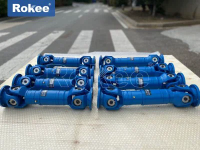
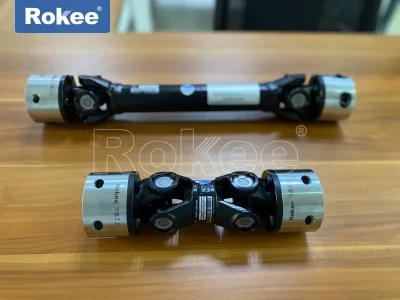
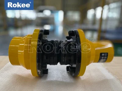
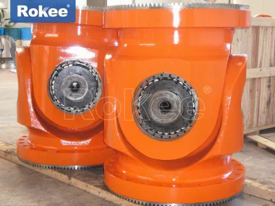
Flange Type Cardan Universal Joint Coupling
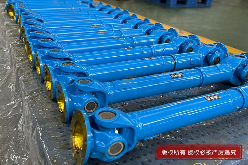
Flange type cardan universal joint coupling represents a sophisticated mechanical transmission component that merges the robust fastening capability of flange connections with the flexible articulation property of cardan joint mechanisms. In complex mechanical systems, perfectly aligned driving and driven shafts are rarely achievable after assembly, and minor shifts caused by thermal expansion, structural deformation, vibration or foundation settlement can generate heavy additional stress on rigid couplings. This coupling addresses that core challenge by transferring torque and rotary motion while accommodating angular misalignment between connected shafts. Unlike couplings that only allow tiny displacement, its cardan joint structure permits substantial angular deflection, making it suitable for equipment layouts where shaft lines are not arranged in a straight line. The flange design at both ends simplifies installation by offering flat mating surfaces secured through bolt assemblies, which distribute clamping force evenly across contact planes and maintain stable connection under cyclic load and shock impact. Engineers often select this design when heavy torque must pass through spatially separated shafts, and disassembly for inspection or component replacement must be completed without full dismounting of adjacent machinery. The basic concept of this coupling draws from the ancient kinematic principle of the cardan hinge, yet modern manufacturing techniques refine material properties and machining precision to adapt the mechanism for heavy-duty continuous operation across a wide range of rotating equipment. Every part of the assembly works in coordination to convert rigid fixed connection into hinged transmission, balancing high torque carrying capacity and flexible alignment compensation in one integrated unit.
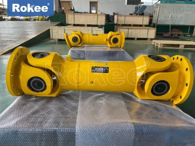
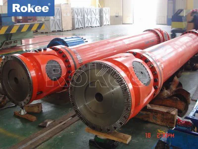
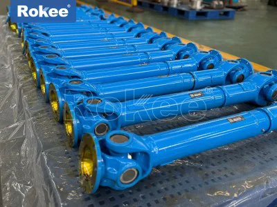
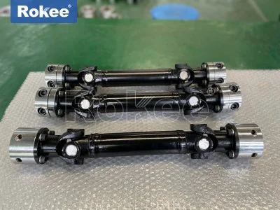
The physical construction of flange type cardan universal joint coupling follows a modular arrangement built around several key subassemblies. At each end, machined flange yokes serve as the interface between the coupling and the connected machine shafts. Each flange yoke features a flat circular flange face with evenly distributed bolt holes and a fork-shaped body extending inward to hold the cross spider assembly. The cross spider, also known as the cross shaft, acts as the central hinge element with four perpendicular trunnions. Precision needle roller bearings fit onto each trunnion, sitting inside the bores machined into the arms of the two yokes. These bearings reduce sliding friction and allow smooth rotational movement between the cross spider and yokes during angular deflection. Some versions include an intermediate tubular shaft linking two universal joint assemblies, while compact configurations use only one single cardan joint paired with two end flanges. Sealing elements are fitted around the bearing housings to block abrasive dust, moisture and process contaminants from entering the bearing cavities, and grease fittings are commonly integrated to replenish lubricant without major disassembly. Every structural component undergoes shaping and heat treatment to enhance surface hardness and internal toughness, because repeated torque reversal and bending load concentrate heavily on the cross spider and bearing surfaces. The flange faces are machined to fine flatness to ensure full contact after bolting; uneven contact would concentrate pressure on limited areas and accelerate loosening under vibration. This carefully assembled chain of parts creates a transmission path that remains mechanically strong while permitting controlled angular movement between the two connected rotating shafts.
Understanding the kinematic behavior of flange type cardan universal joint coupling is essential for proper application and performance prediction. When the driving flange rotates at a steady speed, torque transfers through the flange yoke to the cross spider, then to the opposite yoke and the driven flange. A single cardan joint produces periodic fluctuation in the angular speed of the output shaft when the two shafts operate at an inclined angle. This cyclic speed variation creates minor pulsating torque that increases with the magnitude of working angle. If the working angle remains small, the fluctuation stays low enough for many industrial applications to tolerate. For cases requiring smoother rotation, designers arrange two cardan joints in series. By setting the two yokes of the intermediate shaft in the same plane, the speed variation generated by the first joint cancels out the fluctuation introduced by the second joint, delivering nearly uniform rotary speed to the output side. The hinge action of the cross spider and bearings accommodates continuous angular movement during rotation, but the coupling cannot compensate for unlimited misalignment. Operating angles beyond the designed range will sharply raise bearing load, amplify vibration and shorten service life. Axial displacement can also be accommodated in variants fitted with splined intermediate sections, allowing the overall length of the coupling to adjust as machinery expands thermally or shifts position. The kinematic characteristics define the operating boundaries, so system designers must evaluate expected misalignment and rotation speed during the selection phase to avoid unexpected dynamic loads that harm bearings and connected equipment.
One of the most prominent advantages of flange type cardan universal joint coupling lies in its outstanding torque capacity combined with high angular compensation capability. Many alternative coupling types can only absorb very small angular misalignment, and they suffer premature wear or fracture once shaft inclination exceeds a fraction of a degree. The cardan hinge design allows considerably larger angular deflection, which reduces the strict alignment requirements during equipment installation. The flange connection provides far superior resistance to shock and heavy peak torque compared to clamping or keyed hub connections, because bolts clamp the entire flange face together and spread load over a large contact area. This quality makes the coupling suitable for machinery subjected to sudden load spikes, where impact torque repeatedly strikes the transmission line. The coupling also maintains high mechanical efficiency during operation, with energy loss mainly limited to friction inside the needle bearings. Compared with belt or chain drives, it occupies less space and eliminates the need for tension adjustment, while avoiding slippage under heavy torque. Modular construction supports component replacement; worn bearings or cross spiders can be removed individually without replacing the whole coupling assembly. The design adapts to diverse mounting orientations, including horizontal, inclined and vertical shaft layouts. These benefits make it a preferred choice for power transmission systems where reliable heavy torque transfer must coexist with unavoidable shaft angular deviation.
Even with many attractive functional traits, flange type cardan universal joint coupling carries inherent limitations that must be recognized to prevent operational failure. The speed fluctuation of a single cardan joint creates oscillating forces that excite vibration in the whole mechanical system, especially when rotation speed rises and working angle increases. Such vibration may transfer to bearings and housings of the connected machines, leading to noise, fatigue cracking or sensor reading drift. The bearing assemblies inside the universal joint are wearing parts, and their service life depends heavily on lubrication status, working angle, load magnitude and rotation speed. If lubrication degrades or contaminants breach the seals, bearing wear accelerates rapidly and may progress to seizure. The coupling also cannot compensate for excessive radial offset; large radial misalignment introduces extra bending moments on the cross spider and bearings. Compared with elastomer couplings, it delivers less damping effect to absorb high-frequency vibration, so extra vibration isolation measures may be necessary in sensitive systems. Assembly accuracy also matters when double joint configurations are used. Incorrect phasing of the yokes will fail to cancel speed fluctuation and can worsen dynamic loading. Users must understand these constraints and avoid pushing the coupling beyond its intended working angle or load rating. Recognizing these weaknesses helps engineers decide whether this coupling fits a specific system, or if an alternative transmission solution should be considered instead.
Material selection for flange type cardan universal joint coupling directly determines durability, load resistance and fatigue performance under cyclic operation. The flange yokes and cross spiders are commonly made from forged alloy steel, forging refines the internal grain structure of metal and delivers greater toughness than cast equivalents, making the parts better able to withstand repeated torque reversal and impact loads. After forming, key contact surfaces receive heat treatment to increase surface hardness while keeping the core material ductile. Hardened surfaces resist abrasion from bearing rotation, while the tough inner material prevents brittle fracture under shock. Needle rollers and bearing races use high-carbon bearing steel, polished to extremely smooth surfaces to minimize rolling friction and contact fatigue. Sealing components are made from resilient polymer compounds that resist aging from lubricants and temperature changes, maintaining sealing performance over long running periods. Material choices balance strength, weight and manufacturability. Thick, heavy sections improve load capacity but add rotating mass, which can raise centrifugal force and dynamic imbalance at high rotational speeds. Thin, lightweight construction reduces inertia but sacrifices torque resistance. Material selection also considers ambient operating conditions. In environments with high temperature, special heat-resistant materials are applied to seals and lubricants. In corrosive surroundings, surface treatments protect metal substrates from chemical attack. Every material choice is a careful trade-off tuned to match the thermal, mechanical and environmental demands of the target operating environment.
Installation of flange type cardan universal joint coupling requires careful handling and precise execution to realize full performance and service life. Before mounting, all flange mating surfaces must be cleaned thoroughly to remove rust, paint burrs, grit and residual debris. Any trapped particles between flange faces distort contact pressure and can loosen bolt tension during operation. The two machine flanges should be positioned to keep the operating angle of the universal joint within the designed range. Measurement of shaft inclination is essential; excessive angle immediately raises bearing stress. For double cardan joint arrangements, the angular offset should be distributed evenly between the two joints to balance load. The yoke orientation must be checked carefully to maintain proper phasing, ensuring that speed fluctuations from the two joints counteract each other. Fasteners are tightened in a staggered sequence to achieve uniform preload across all flange bolts, avoiding uneven clamping force that warps the flange or loosens some bolts over time. After bolting, manual rotation of the full shaft line is recommended to verify free movement and detect binding or abnormal friction. Once initial startup occurs, operators should observe vibration and noise. Unusual vibration often signals incorrect alignment, wrong yoke phasing or insufficient bolt tension. A running-in period under partial load is advisable for new installations, allowing bearing surfaces to settle before applying full working torque. Proper installation is not merely a mechanical assembly task; it establishes the baseline operating condition that determines how well the coupling performs over its service cycle.
Maintenance practice for flange type cardan universal joint coupling focuses on preserving lubrication, monitoring wear and detecting early signs of component degradation. Lubricant serves multiple purposes: it reduces rolling friction inside needle bearings, dissipates localized heat generated by contact stress, and forms a protective barrier against corrosion. Grease replenishment intervals depend on operating speed, temperature, load and environmental cleanliness. Heavy-duty continuous operation requires more frequent lubrication, while intermittent duty extends the interval. During routine checks, technicians inspect seals for cracks, hardening or leakage. Damaged seals allow contaminants to enter bearing chambers and degrade lubricant quickly. Visual inspection can reveal loose flange bolts, surface cracks on yokes or cross spiders, and signs of metal powder from bearing wear. Vibration monitoring offers another effective method to track component condition. Rising vibration amplitude typically indicates bearing wear, increased misalignment or bolt loosening. When disassembly becomes necessary, components should be inspected for pitting, spalling or fatigue cracks on bearing raceways and cross trunnions. Parts showing surface damage must be replaced instead of reused, because microcracks propagate under cyclic torque and may lead to sudden failure. Maintenance records help track operating hours and identify trends of degradation. A well-structured maintenance routine prevents unexpected breakdowns and extends the usable lifespan of the coupling, reducing unplanned downtime for the whole mechanical system.
Flange type cardan universal joint coupling finds broad application across a wide spectrum of heavy machinery systems where flexible torque transmission is required. Material handling equipment frequently adopts this coupling to connect drive units with conveyor mechanisms, where frame deflection and uneven foundation settlement create persistent shaft angular deviation. Processing machinery that handles bulk materials often experiences shock loading during start-up and product impact, and the coupling’s flange connection reliably withstands such peak torque. Mobile industrial machinery also relies on this coupling for power transfer between prime movers and working assemblies, where relative movement between machine sections changes shaft alignment during operation. Many rotary equipment packages use the coupling to link prime movers to driven rotors, simplifying layout design by removing the strict requirement for perfectly collinear shafts. It is also applied in test benches and power measurement systems, where adjustable shaft angles are intentionally set for dynamic performance testing. The coupling’s versatility comes from its ability to adapt to variable working angles and heavy torque, but application selection always considers rotation speed, ambient temperature, contamination level and expected service interval. In every scenario, engineers weigh the dynamic behavior of the cardan joint against system vibration tolerance. Properly matched to the operating conditions, this coupling delivers dependable power transmission and reduces mechanical stress imposed on connected machine components.
The future development of flange type cardan universal joint coupling centers on advanced manufacturing methods, optimized geometry and improved tribological solutions to expand performance boundaries. Modern machining techniques deliver tighter dimensional tolerance and superior surface finish, lowering friction and reducing internal dynamic imbalance. Advanced simulation tools allow designers to model stress distribution, heat generation and vibration response under complex load cycles, refining the contour of yokes and cross spiders to eliminate stress concentration points. New bearing and seal formulations enhance performance in extreme thermal and dusty environments, extending service intervals and lowering maintenance demand. Some designs integrate embedded sensing elements to track temperature and vibration continuously, enabling condition-based maintenance rather than fixed-interval servicing. Lightweight yet high-strength material options help cut rotating inertia, supporting higher rotational speeds without sacrificing torque capacity. These developments do not alter the fundamental kinematic principle of the cardan joint, but they expand the usable operating window and improve reliability in challenging industrial environments. As mechanical systems continue to demand higher power density and longer service life, the flange type cardan universal joint coupling will keep evolving as a key transmission solution. It remains a practical engineering choice that balances proven mechanical principles with modern manufacturing innovation, supporting efficient power transfer for rotating machinery with misaligned shaft arrangements.