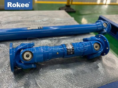
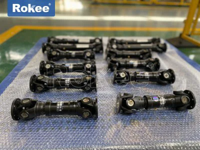
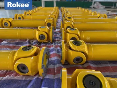
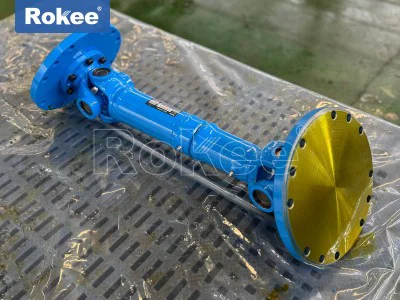
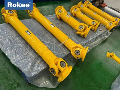
Cardan Drive Shaft For Steel Plant

Within the complex mechanical ecosystem of a steel plant, the cardan drive shaft stands as one of the most indispensable transmission components, quietly delivering rotational power across production lines that face extreme working conditions every single day. Also commonly referred to as a universal joint shaft, this mechanical assembly acts as a flexible bridge between power output units and driven equipment, solving the core challenge of torque transfer when connected shafts cannot maintain perfect coaxial alignment. Steel production processes involve continuous heavy loading, thermal expansion of metal frames, structural deformation under impact force, and minor displacement of machine bases, all of which make rigid shaft connections impractical and prone to sudden fracture. A cardan drive shaft is built to accommodate these dynamic changes, accepting angular offset and limited axial movement while maintaining stable power transmission. Unlike ordinary transmission couplings that can only handle tiny misalignment values, the universal joint structure at both ends of the shaft permits controlled angular deflection during operation, ensuring that power can still flow consistently even when the relative position between driving and driven ends shifts. For steel plants that run nonstop production cycles, the reliability of this component directly affects overall line continuity. Any unexpected failure in the drive shaft will force an entire rolling or casting segment to halt, triggering cascading losses in material processing and operational efficiency. This fundamental role explains why steel plant engineering teams spend significant effort on selecting, installing, and monitoring cardan drive shafts for every heavy-duty rotating station throughout the metallurgical workflow.
The basic working principle of a cardan shaft relies on the geometry of paired universal joints, which smooth out speed fluctuations that would otherwise occur with a single universal joint. Each universal joint consists of yokes, a cross-shaped spider, and needle roller bearings nested inside the yoke ends. When the driving yoke rotates, motion transfers to the cross spider, which pivots within the bearing sets to adapt to angular deviation before passing rotation to the second yoke. When two universal joints are properly phased and arranged at matching angles, the velocity variation generated by the first joint cancels out through the second joint, delivering steady rotational speed to the driven side. This mechanical design is especially valuable for rolling mill stands, where the entry of thick steel slabs creates sudden shock loads and temporary axis displacement. As hot metal passes through rolling rolls, the mill housing experiences instantaneous force and thermal distortion, shifting the relative position between the gearbox output flange and the roll input end. A rigid connection would transmit all these stress spikes directly to gear teeth and motor bearings, accelerating fatigue damage. The cardan drive shaft absorbs these dynamic offsets and shock impacts, isolating the main drive system from irregular mechanical stress. Even with continuous cyclic loading, the balanced rotation of the assembly keeps vibration levels within acceptable ranges, protecting both upstream and downstream equipment and preventing surface defects on steel products caused by unstable roll speed during forming operations.
Material selection forms the foundation of a cardan drive shaft’s ability to survive steel plant environments, where high temperature, abrasive dust, heavy torsion, and repeated impact combine to accelerate component aging. The main shaft tube is normally fabricated from high-strength alloy steel, chosen for excellent torsional resistance, fatigue performance, and resistance to thermal softening under radiant heat from hot steel. Hollow shaft tube designs are widely adopted because they deliver high torque capacity while reducing overall rotating mass, which lessens dynamic load on bearings and joints during acceleration and deceleration. The cross spider and bearing journals undergo specialized heat treatment processes to increase surface hardness while retaining inner material toughness, resisting indentation and wear under continuous contact pressure. Yoke components are forged rather than cast to eliminate internal voids and defects that could become crack initiation points under cyclic shock loads. Needle roller bearings inside the joint assemblies are engineered to bear heavy radial loads and maintain low friction, even when fine oxide scale and dust drift into the surrounding area. Protective sealing structures are fitted around bearing chambers to block abrasive particles from entering the contact zone, as steel scale particles act as grinding powder once trapped between bearing surfaces and cross journals. Without carefully selected materials and precise heat treatment, the universal joints would quickly develop excessive clearance, generate intense vibration, and eventually fail prematurely amid the harsh thermal and mechanical cycles of steel production.
Cardan drive shafts serve multiple key stations across the full steel manufacturing workflow, with the most prominent applications found in hot rolling, cold rolling, and continuous casting sections. In hot rolling lines, these shafts connect the reduction gearboxes to the work rolls and backup rolls of mill stands, transferring enormous torque to squeeze red-hot slabs into thinner strips or profiles. Each time a slab enters the roll gap, the shaft must absorb sharp impact torque before settling into steady rolling torque as the metal flows through the rolls. In cold rolling mills, the working environment has lower ambient temperature but stricter requirements for rotational stability, since minor speed fluctuations can create uneven thickness patterns on finished steel sheets. Continuous casting machines also depend heavily on cardan drive shafts to drive pinch rolls and withdrawal units, pulling semi-solid steel strands out of the mold at precisely controlled speeds. Beyond these core areas, the shafts appear on auxiliary metallurgical equipment including ladle turret drives, roller table drives, and straightening machines, wherever heavy torque needs to cross variable shaft alignment. Different application positions require adjustments in shaft length, joint size, telescopic structure, and sealing configuration. Some installations use telescopic cardan shafts to compensate for axial movement caused by thermal expansion of machine frames, while shorter compact versions fit into confined spaces of finishing mill groups. This wide adaptability makes cardan drive shafts a universal transmission solution covering nearly all rotating heavy machinery within steelmaking facilities.
Environmental hazards inside steel plants create unique operational challenges for cardan drive shafts that do not exist in lighter industrial settings. Hot rolling areas radiate intense heat from steel slabs and coils, raising component surface temperatures and degrading lubricant performance over time. Fine iron oxide scale continuously flakes off hot steel surfaces, filling the air with hard particulate matter that settles on every mechanical assembly. High humidity sometimes appears near cooling water spray zones, creating conditions for surface oxidation on exposed metal parts. Meanwhile, repeated shock loading creates cyclic fatigue stress that slowly accumulates in the cross spider, yokes and weld or flange connections. All these factors work together to accelerate wear and shorten service life if the shaft lacks proper protection. Heat can thin lubricating grease and reduce its load-bearing capacity, leading to metal-to-metal contact inside bearings and rapid scoring of journal surfaces. Abrasive dust can bypass worn seals and grind away bearing raceways, increasing joint clearance and generating stronger vibration. Fatigue cracks may start at sharp corners or stress concentration points on yokes after countless torque cycles. Even if a crack is tiny at first, continued rotation under heavy load can make it expand rapidly until a sudden fracture occurs. Designers account for these risks by adding reinforced sealing systems, selecting high-temperature lubricant formulas, optimizing structural transitions to reduce stress concentration, and applying surface protective coatings on exposed shaft sections to resist corrosion and scale adhesion.
Dynamic balancing is a critical manufacturing step for cardan drive shafts intended for steel plant service, directly influencing vibration behavior and equipment lifespan. Every rotating mass contains minor inherent imbalance from material density variation, machining tolerances, and assembly offset. When the shaft spins at operational speed, imbalance creates centrifugal force that excites vibration across the entire drive train. In steel mills, vibration from an unbalanced cardan shaft propagates to mill housings, gearboxes and electric motors, loosening fasteners, damaging bearing seats and amplifying noise throughout the workshop. Severe imbalance can also worsen uneven wear on universal joint bearings and cross journals, shortening maintenance intervals significantly. Balancing procedures are carried out after full assembly, treating the complete unit including shaft tube, yokes, joint components and flanges as a single rotating body. Correction weights are added or material removed at designated positions to reduce residual imbalance to acceptable levels. After balancing, the shaft will operate smoothly within its designed speed range, minimizing dynamic stress on connected machinery. This process becomes even more important for longer cardan shafts used in wide rolling stands, as longer rotating bodies are more sensitive to small imbalance errors. Even though balancing adds production steps, steel plant operators recognize that well-balanced drive shafts reduce unplanned downtime and lower long-term repair costs by protecting the whole transmission system from vibration-related damage.
Installation quality determines whether a cardan drive shaft can deliver its designed service life, and steel plant maintenance teams follow strict operational practices during fitting and commissioning. Before installation, technicians inspect flange contact surfaces for burrs, deformation or trapped scale particles that would prevent flat mating between connecting flanges. Fasteners are tightened in a proper sequence to ensure uniform clamping force, avoiding uneven flange loading that could create bending stress on the shaft body. Correct phasing of the two universal joints is essential, because misphased joints will not cancel speed fluctuations and will produce pulsating torque and vibration during rotation. Operators also carefully control the working angular deflection within the designed range; excessive operating angles dramatically increase bearing friction, heat generation and fatigue load on the cross spider. Laser alignment tools help verify the relative position between driving and driven flanges, checking both static alignment and expected displacement under hot working conditions. The mounting layout must avoid undesirable double bend configurations that introduce extra bending stress into the shaft assembly. After physical installation, the unit undergoes no-load trial rotation to listen for abnormal noise and measure baseline vibration levels before steel processing resumes. Any unusual vibration or knocking sound detected during trial run indicates alignment error, incorrect phasing or pre-existing component damage, which must be corrected before applying full production load. Careful installation reduces avoidable failure modes and helps the cardan drive shaft perform reliably through thousands of operating hours.
Routine maintenance represents the most effective way to extend the service life of cardan driveshafts in steel plants, with lubrication standing as the core task of any service schedule. Lubricant fills the space between needle rollers, cross journals and bearing cups, forming an oil film to separate metal contact surfaces, reduce friction and dissipate heat generated inside universal joints. Working conditions dictate lubrication frequency: shafts operating in high-temperature hot rolling zones require more frequent regreasing than those in cooler processing areas. Maintenance staff clean grease fittings before injection to prevent dirt from being pushed into bearing chambers, and they continue adding grease until old contaminated lubricant discharges from relief ports, confirming full replacement. Visual inspections check for loose fasteners, damaged sealing boots, surface corrosion and accumulated scale buildup on the shaft body. Vibration monitoring is performed at regular intervals to track changes in vibration amplitude, which serves as an early warning signal of growing joint clearance, bearing wear or loosened connections. During periodic shutdowns, teams check internal clearances of cross and bearing assemblies, and perform non-destructive checks on yokes and cross spiders to detect hidden fatigue cracks. When wear exceeds acceptable limits, worn components get replaced rather than waiting for catastrophic breakdown. Neglected maintenance leads to progressive degradation: depleted lubricant causes bearing seizure, damaged seals allow abrasive scale ingress, and undetected cracks eventually lead to shaft breakage that interrupts production for extended periods.
Operational monitoring and fault diagnosis help steel plant teams identify early warning signs of cardan drive shaft degradation before failures occur. Sensors mounted on bearing housings and mill frames track vibration patterns, temperature rises and noise signatures during continuous operation. Rising temperature at universal joint points often signals insufficient lubrication, bearing wear or excessive working angle. Changes in vibration spectrum reveal developing clearance inside joints or fatigue cracking in yoke structures. Experienced maintenance personnel can also identify abnormal operating conditions through sound; regular rotation produces steady low-frequency noise, while damaged bearings or loose joints create sharp knocking or rumbling sounds synchronized with shaft rotation. Historical operational data from each cardan drive shaft can be recorded and compared over time, establishing performance trends to predict remaining service life and schedule component replacement during planned maintenance windows. This predictive approach reduces surprise equipment failures and avoids emergency shutdowns that disrupt steel production sequences. Operators also keep records of shock load incidents, overload events and thermal excursions, because these events accelerate fatigue damage and may require accelerated inspection cycles. By combining real-time monitoring and periodic physical checks, steel plants shift from reactive breakdown repair to proactive asset management for cardan drive shafts across all production lines.
As steel production technology continues to evolve, the design and application of cardan drive shafts keep advancing to meet higher demands for productivity and equipment durability. Modern steel plants pursue longer continuous operation cycles, larger rolling forces, and tighter control over steel product quality, all of which place greater requirements on transmission system stability. Design refinements include optimized forging contours to reduce stress concentration, improved sealing structures that resist high temperature and abrasive dust, and advanced bearing configurations that carry heavier loads with lower friction. Some upgraded cardan shaft designs integrate better thermal compensation features, adapting to larger thermal displacement between connected equipment components. Manufacturing processes also benefit from improved machining precision and heat treatment control, enhancing material fatigue resistance and consistency across production batches. Digital monitoring integration becomes more common, allowing operating data of cardan drive shafts to feed into plant-wide asset management platforms, automatically alerting maintenance teams when performance indicators drift beyond normal ranges. These improvements do not change the fundamental working principle of universal joint transmission, but they expand operational limits, extend service intervals, and lower overall operational risk for steel facilities. For the future of steel manufacturing, cardan drive shafts will remain a vital mechanical link, continuously evolving to match the demanding operating environment and reliability expectations of modern metallurgical production lines.