Principle Of Cross Axis Universal Joint Coupling

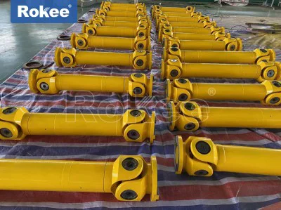
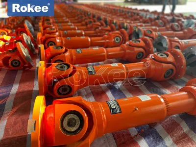
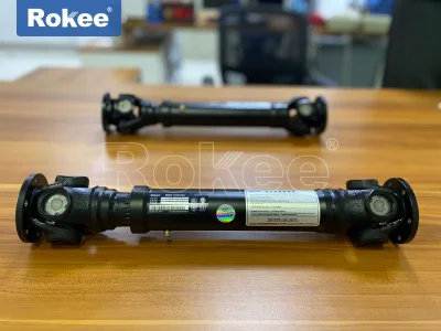
The cross axis universal joint coupling mainly consists of four basic components: two fork joints, a cross axis, and four needle roller bearings. The subtlety of this structure lies in its combination of symmetry and movable connections.
Each universal joint coupling fork is usually connected to the drive shaft and driven shaft through flanges or splines. The cross shaft serves as the core component, with its four necks connected to two universal joint coupling forks through high-precision needle roller bearings. The bearing design not only reduces friction losses, but also can withstand higher radial loads. Modern high-performance universal couplings use forged cross shafts made of special alloy steel, with a surface treated with carburizing and quenching to ensure durability under heavy load conditions.
The kinematic characteristics of the cross axis universal joint coupling demonstrate the ingenious application of classic mechanical principles. When the input shaft and output shaft form a certain angle, the cross shaft generates complex spatial motion to coordinate the speed difference between the two shafts.
From a mechanical perspective, the cross axis universal joint coupling bears complex composite loads during operation. During the torque transmission process, the cross axis mainly bears torsional and bending stresses, while the needle roller bearings bear alternating contact stresses.
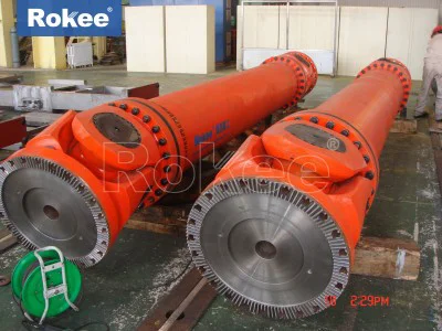
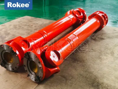
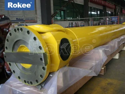
Cross axis universal couplings are widely used in various industrial fields, and their design continues to evolve with application requirements. In automotive transmission systems, lightweight design reduces weight by 30% while increasing strength; In steel mills, heavy-duty couplings can transmit torque exceeding 1000kN · m; In precision machine tools, special balancing technology controls vibration below 0.05mm/s.
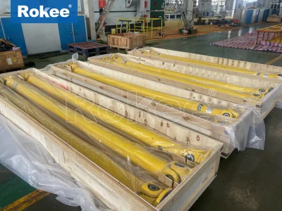
Proper selection and maintenance are crucial for maximizing the performance of cross axis universal couplings. When selecting, it is necessary to comprehensively consider factors such as torque capacity, speed limit, allowable deflection angle, and environmental conditions.
-
![Cardan Shaft Empowers PU Sandwich Panel Machine For More Precise Transmission]()
Cardan Shaft Empowers PU Sandwich Panel Machine For More Precise Transmission
-
![Troubleshooting And Emergency Treatment Of Universal Coupling In PU Sandwich Panel Line]()
Troubleshooting And Emergency Treatment Of Universal Coupling In PU Sandwich Panel Line
-
![Perfect Adaptation Scheme Of Universal Shaft Coupling And Sandwich Panel Line]()
Perfect Adaptation Scheme Of Universal Shaft Coupling And Sandwich Panel Line
-
![Selection And Application Skills Of Universal Coupling For Sandwich Panel Production Line]()
Selection And Application Skills Of Universal Coupling For Sandwich Panel Production Line
-
![Drive Shaft Coupling]()
Drive Shaft Coupling
-
![High Rigidity Universal Shaft]()
High Rigidity Universal Shaft
-
![Welded Universal Shaft]()
Welded Universal Shaft
-
![Single Joint Universal Shaft]()
Single Joint Universal Shaft