Complete Guide For Installation And Commissioning Of Universal Shaft Coupling In Sandwich Panel Line
The universal shaft coupling is a critical component in the sandwich panel production line, serving as the core connection that transmits rotational power between different mechanical units, such as the unwinding mechanism, forming rollers, cutting equipment, and transmission motors. Its proper installation and commissioning directly determine the stability of the entire production line, the quality of the sandwich panels produced, and the service life of the equipment. Unlike rigid couplings that require absolute alignment between two shafts, the universal shaft coupling can compensate for angular, radial, and axial displacements caused by manufacturing errors, installation deviations, load deformation, and temperature changes, making it indispensable in the complex working environment of sandwich panel production. This guide provides a comprehensive, step-by-step overview of the installation and commissioning process of the universal shaft coupling in a sandwich panel line, focusing on practical operations, key precautions, and troubleshooting methods to ensure that the coupling operates efficiently and reliably under various working conditions.
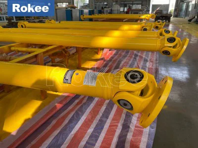
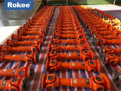
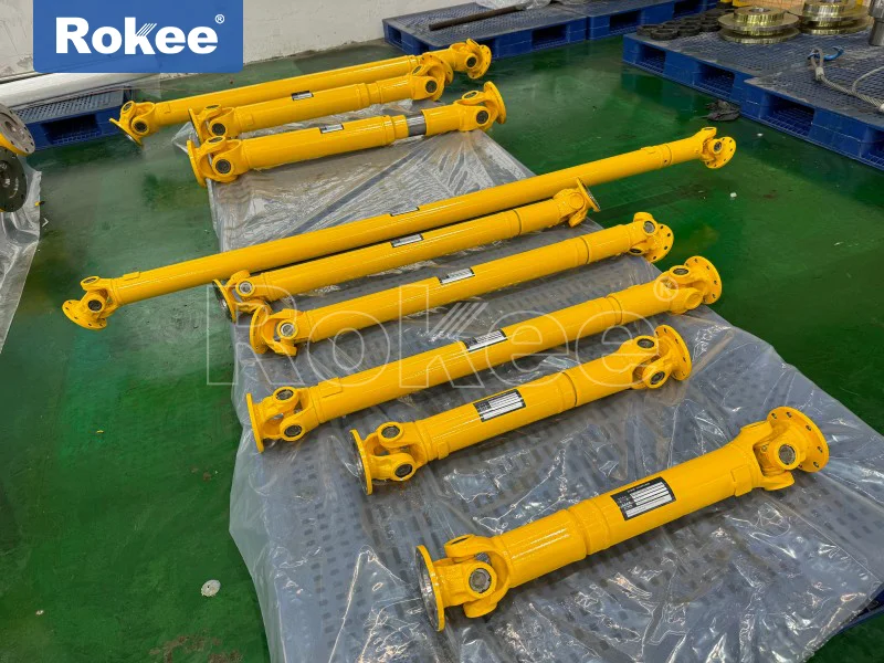
Before starting the installation process, adequate preparation work is essential to avoid delays, errors, or equipment damage during installation. The first step in preparation is to conduct a thorough inspection of the universal shaft coupling components. The core components of a typical universal shaft coupling include the cross shaft, bearing assemblies, fork-shaped heads (either integral or split), expansion splines, and connecting bolts. Each component should be carefully checked for cracks, deformation, rust, or excessive wear. Special attention should be paid to the cross shaft and bearing assemblies, as these are the key torque-transmitting parts; any sign of damage, such as pitting on the cross shaft surface or seizing of the bearings, can lead to serious malfunctions during operation. The expansion splines, which compensate for axial displacement, should be inspected to ensure smooth sliding without jamming, and the connecting bolts should be checked for thread integrity and surface damage. Additionally, the mating surfaces of the coupling, including the shaft holes and flange faces, should be cleaned thoroughly to remove oil, dust, rust, and other contaminants. Even small particles of debris can affect the fit accuracy between the coupling and the shafts, leading to uneven force distribution and increased vibration during operation. A clean, smooth mating surface is crucial for ensuring a secure connection and reducing wear over time.
In addition to component inspection and cleaning, it is necessary to verify that the specifications of the universal shaft coupling match the actual working conditions of the sandwich panel line. The key parameters to check include the rated torque, allowable rotational speed, maximum allowable angular deviation, and axial compensation range. The rated torque of the coupling should be sufficient to handle the maximum torque generated by the transmission system, considering factors such as peak loads during start-up and sudden changes in production speed. The allowable angular deviation, which typically ranges from 5° to 45° for most universal shaft couplings used in sandwich panel lines, should be compatible with the misalignment between the connected shafts. If the actual angular deviation exceeds the coupling’s limit, it will cause excessive stress on the cross shaft and bearings, leading to premature wear and failure. The rotational speed of the coupling should also match the operating speed of the production line; for high-speed applications (exceeding 1000 rpm), additional dynamic balance checks may be required to prevent vibration caused by centrifugal force. It is also important to prepare the necessary installation tools in advance, including torque wrenches, laser alignment tools, dial indicators, screwdrivers, wrenches, and cleaning rags. The torque wrench should be calibrated to ensure accurate torque application, as over-tightening or under-tightening of bolts can lead to connection failures or component damage. Laser alignment tools or dial indicators are essential for achieving precise alignment between the connected shafts, which is a critical factor in the coupling’s performance and service life.
Once the preparation work is completed, the installation process can begin, starting with the installation of the coupling halves on the respective shafts. The first step is to mount one half of the coupling onto the drive shaft (connected to the motor) and the other half onto the driven shaft (connected to the equipment, such as forming rollers or unwinding mechanisms). Before installation, the shaft surfaces should be lightly coated with a thin layer of lubricating oil to facilitate assembly and prevent corrosion. The coupling halves should be pressed onto the shafts smoothly, ensuring that they are seated firmly against the shaft shoulders or positioning sleeves. It is important to avoid using excessive force or hammering during installation, as this can damage the shaft surfaces, the coupling’s internal components, or the bearings. If the coupling is a press-fit type, a hydraulic press or appropriate pressing tool should be used to ensure uniform force application. For split-type coupling halves, the two parts should be aligned correctly and fastened securely with the provided bolts before mounting onto the shaft.
After mounting the coupling halves on the respective shafts, the next critical step is to align the two shafts. Shaft alignment is essential because even minor misalignment can cause severe vibration, increased wear on the coupling components and bearings, and reduced transmission efficiency. The alignment process involves checking and adjusting both angular misalignment (where the shafts are not parallel) and radial misalignment (where the shafts are offset from each other). For most sandwich panel line applications, the allowable angular deviation should not exceed 1°, and the radial deviation should not exceed 0.1 mm per meter of shaft length. To achieve precise alignment, a laser alignment tool is recommended, as it provides higher accuracy than traditional methods such as using a straightedge or feeler gauge. The laser alignment tool is mounted on both coupling halves, and the alignment data is displayed in real time, allowing the operator to adjust the position of the motor or driven equipment accordingly. Adjustments can be made by adding or removing shims under the motor base or adjusting the mounting bolts of the driven equipment. It is important to make small, incremental adjustments and recheck the alignment after each adjustment to avoid overcorrecting. Once the alignment is within the allowable range, the mounting bolts of the motor and driven equipment should be tightened to the specified torque to secure the position.
With the coupling halves mounted and the shafts aligned, the next step is to assemble the universal shaft coupling. This involves connecting the two coupling halves using the cross shaft and bearing assemblies. The cross shaft should be inserted into the bearing bores of both coupling halves, ensuring that the bearings are properly seated and that the cross shaft can rotate freely without jamming. Before assembly, the cross shaft and bearing surfaces should be coated with an appropriate lubricant, such as lithium-based grease, to reduce friction and wear. The type of lubricant should be selected based on the operating conditions; for high-temperature or heavy-load environments, a high-temperature grease with excellent thermal stability and load-carrying capacity should be used. After inserting the cross shaft, the retaining rings or caps should be installed to secure the bearings in place and prevent axial movement. It is important to ensure that the retaining rings are properly seated and that there is no excessive play in the cross shaft assembly. Once the coupling is fully assembled, a manual rotation test should be performed to check for smooth operation. The coupling should rotate freely without any binding, clicking, or unusual noise, which would indicate a problem with the assembly or alignment.
After the installation is completed, the commissioning process begins to verify the performance of the universal shaft coupling and ensure that it operates correctly under actual working conditions. The commissioning process is divided into three main stages: no-load test, load test, and long-term operation test. Each stage is designed to identify potential issues and ensure that the coupling meets the required performance standards.
The no-load test is the first stage of commissioning and involves running the production line without any raw materials or load. Before starting the no-load test, a final inspection should be performed to ensure that all connections are secure, the lubrication is sufficient, and the alignment is correct. The motor should be started slowly, and the coupling should be monitored for vibration, noise, and temperature. The vibration level should be within the acceptable range; excessive vibration may indicate misalignment, loose connections, or damaged components. Unusual noises, such as grinding, clicking, or squealing, should be investigated immediately, as they may be a sign of bearing failure, cross shaft damage, or improper assembly. The temperature of the coupling, particularly the bearing areas, should be monitored using an infrared thermometer or temperature probe. The normal operating temperature of the bearing should not exceed 70°C; if the temperature rises rapidly or exceeds this limit, it may indicate insufficient lubrication, over-tightening of components, or bearing damage. The no-load test should be run for at least 30 minutes, and any abnormalities should be addressed before proceeding to the load test.
Once the no-load test is completed successfully, the load test can begin. The load test involves running the production line with actual raw materials and operating at the normal production speed. During the load test, the performance of the universal shaft coupling is monitored under realistic working conditions. The key parameters to monitor include torque transmission, vibration, noise, temperature, and the coupling’s ability to compensate for displacements. The torque transmission should be stable, with no sudden fluctuations that could indicate slippage or component failure. The vibration level should remain within the acceptable range, even under full load; if vibration increases significantly under load, it may indicate that the alignment is not precise enough or that the coupling is not properly sized for the application. The noise level should be consistent and free of any unusual sounds, and the temperature of the coupling should not exceed the recommended limit. Additionally, the expansion splines should be checked to ensure that they are sliding smoothly to compensate for axial displacement caused by thermal expansion or load changes. The load test should be run for at least 2 hours, and the coupling should be inspected periodically during the test for any signs of wear, damage, or leakage of lubricant. If any issues are identified during the load test, the production line should be shut down immediately, and the problem should be resolved before continuing.
The final stage of commissioning is the long-term operation test, which involves running the production line continuously for an extended period (typically 24 to 48 hours) under normal operating conditions. This test is designed to verify the durability and reliability of the universal shaft coupling over time. During the long-term operation test, regular inspections should be performed to check the coupling’s condition, including the tightness of connecting bolts, the level of lubrication, and the presence of any wear or damage. The bolts should be checked and retightened if necessary, especially after the first 50 hours of operation, to compensate for any initial settling or loosening. The lubricant level should be checked regularly, and additional lubricant should be added as needed to ensure that all moving parts are properly lubricated. The coupling should also be inspected for any signs of corrosion, particularly in humid or corrosive environments, and appropriate measures should be taken to protect the components, such as applying anti-rust oil or using corrosion-resistant materials. At the end of the long-term operation test, the coupling should be disassembled and inspected thoroughly to check for wear on the cross shaft, bearings, and splines. If any components are worn beyond the acceptable limit, they should be replaced to ensure continued reliable operation.
Proper maintenance is essential to extend the service life of the universal shaft coupling and ensure the long-term stability of the sandwich panel production line. A regular maintenance schedule should be established, including periodic lubrication, inspection, and component replacement. Lubrication is one of the most critical maintenance tasks, as it reduces friction between moving parts and prevents premature wear. The lubrication cycle should be determined based on the operating conditions: for normal working conditions, lubrication should be performed every 300 to 500 hours or every 3 months; for harsh conditions, such as high temperature, high load, or dusty environments, the lubrication cycle should be shortened to every 100 to 200 hours or every month. When lubricating, the old grease should be completely removed before adding new grease to prevent contamination. The grease should be injected through the grease fitting until it overflows from the drain hole, ensuring that all bearing surfaces are fully coated. For couplings without grease fittings, the coupling should be disassembled, and the bearings should be manually lubricated.
Regular inspections should be performed to check for wear, damage, or misalignment. The cross shaft, bearings, and splines should be inspected every 3 to 6 months for signs of wear, cracks, or corrosion. The wear limit for the cross shaft is typically 2% to 3% of its diameter; if the wear exceeds this limit, the cross shaft should be replaced immediately. The spline clearance should also be checked; if the clearance exceeds 1.5 times the initial value, the splines should be replaced or repaired. The connecting bolts should be inspected every 500 hours to ensure that they are tight; any loose bolts should be tightened to the specified torque, and any damaged bolts should be replaced. The alignment of the shafts should be checked every 6 months or during equipment overhauls to ensure that it remains within the allowable range. If misalignment is detected, adjustments should be made promptly to prevent excessive stress on the coupling components.
Troubleshooting is an important part of ensuring the reliable operation of the universal shaft coupling. Common issues that may occur during operation include abnormal vibration, unusual noise, overheating, lubricant leakage, and torque transmission failure. Each of these issues has specific causes and solutions that should be addressed promptly to avoid further damage to the coupling or other components of the production line.
Abnormal vibration is one of the most common issues and is often caused by misalignment of the shafts, loose connections, worn bearings, or unbalanced coupling components. If vibration is detected, the first step is to check the alignment of the shafts using a laser alignment tool or dial indicator. If misalignment is found, adjustments should be made to correct it. Loose connecting bolts should be tightened to the specified torque, and any damaged bolts should be replaced. Worn bearings should be replaced, and the coupling should be re-lubricated. If the vibration persists after these checks, the coupling components should be inspected for damage or imbalance; for high-speed applications, a dynamic balance test may be required to correct any imbalance.
Unusual noise, such as grinding, clicking, or squealing, is typically caused by worn bearings, damaged cross shafts, or insufficient lubrication. Grinding or squealing noises often indicate that the bearings are worn or lack lubrication; in this case, the bearings should be replaced and the coupling re-lubricated. Clicking noises may be caused by loose or damaged cross shaft components; the cross shaft should be inspected and replaced if necessary. It is important to address unusual noises immediately, as they can be a sign of serious component damage that could lead to coupling failure if left unaddressed.
Overheating of the coupling is usually caused by insufficient lubrication, over-tightening of components, misalignment, or bearing failure. If the coupling temperature exceeds 70°C, the production line should be shut down immediately to prevent damage. The first step is to check the lubricant level and quality; if the lubricant is insufficient or contaminated, it should be replaced. The alignment of the shafts should be checked and adjusted if necessary. Over-tightened components should be loosened to the specified torque, and worn bearings should be replaced. If the overheating persists, the coupling may be overloaded, and the torque capacity should be re-evaluated to ensure that it is sufficient for the application.
Lubricant leakage can occur due to damaged seals, loose retaining rings, or over-filling of lubricant. Damaged seals should be replaced immediately to prevent lubricant loss and contamination of the coupling components. Loose retaining rings should be tightened or replaced to ensure a secure seal. If the lubricant is over-filled, the excess should be drained to the appropriate level to prevent leakage.
Torque transmission failure is a serious issue that can cause the production line to stop. This issue is often caused by broken cross shafts, worn splines, or loose connecting bolts. A broken cross shaft typically occurs due to overload, fatigue, or improper installation; the cross shaft should be replaced with a new one of the correct specification. Worn splines can be repaired or replaced, depending on the extent of the wear. Loose connecting bolts should be tightened to the specified torque, and any damaged bolts should be replaced. It is important to identify the root cause of the torque transmission failure to prevent it from recurring, such as ensuring that the coupling is properly sized for the application and that the load does not exceed the rated torque.
In conclusion, the installation and commissioning of the universal shaft coupling in a sandwich panel line is a critical process that requires careful preparation, precise operation, and thorough testing. By following the steps outlined in this guide, operators can ensure that the coupling is installed correctly, aligned properly, and commissioned to operate efficiently and reliably. Regular maintenance and prompt troubleshooting are essential to extend the service life of the coupling, reduce downtime, and ensure the consistent quality of the sandwich panels produced. The universal shaft coupling’s ability to compensate for misalignments and transmit torque reliably makes it a vital component in the sandwich panel production line, and proper care and attention to its installation and maintenance will contribute to the overall efficiency and profitability of the production process. Whether you are installing a new coupling or maintaining an existing one, adhering to these guidelines will help to minimize issues and maximize the performance of the equipment.
-
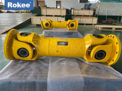
![Cardan Shaft Coupling Combination For PU Sandwich Panel Machine is Efficient Operation]()
Cardan Shaft Coupling Combination For PU Sandwich Panel Machine is Efficient Operation
-
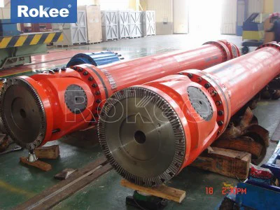
![Universal Shaft Coupling Upgrade For Sandwich Panel Machine To Further Improve Efficiency]()
Universal Shaft Coupling Upgrade For Sandwich Panel Machine To Further Improve Efficiency
-
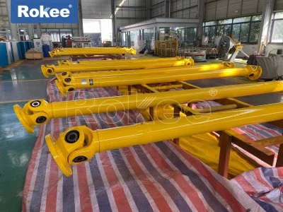
![Universal Shaft Adapted To Polyurethane Sandwich Panel Machine To Boost Production Capacity]()
Universal Shaft Adapted To Polyurethane Sandwich Panel Machine To Boost Production Capacity
-
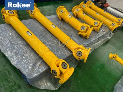
![Daily Inspection And Maintenance Process Of Universal Coupling In Sandwich Panel Making Line]()
Daily Inspection And Maintenance Process Of Universal Coupling In Sandwich Panel Making Line
-
![Energy-saving Transformation Scheme Of Universal Joint Coupling Adapting To Polyurethane Sandwich Panel Making Line]()
Energy-saving Transformation Scheme Of Universal Joint Coupling Adapting To Polyurethane Sandwich Panel Making Line
-
![Crane Cardan Shaft]()
Crane Cardan Shaft
-
![Ball Cage Cardan Coupling]()
Ball Cage Cardan Coupling
-
![Core Role Of Cardan Driveshaft In Sandwich Panel Making Equipment]()
Core Role Of Cardan Driveshaft In Sandwich Panel Making Equipment