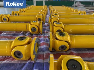
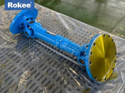
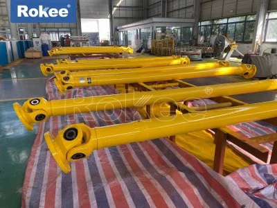
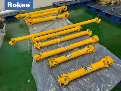
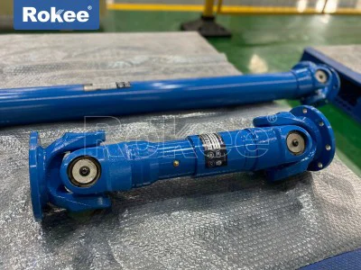
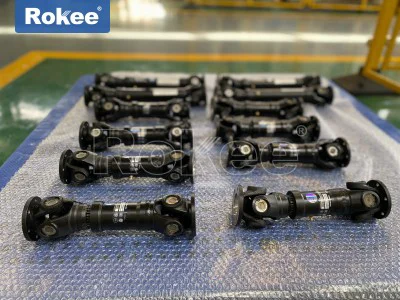
Custom Universal Joint Coupling

Custom universal joint coupling represents a specialized form of power transmission component engineered to transfer rotational torque and motion between two shafts that cannot maintain perfect collinear alignment during operation. Unlike off-the-shelf coupling units built around fixed dimensional parameters and predefined load limits, custom universal joint couplings are developed from the ground up to match the unique geometric constraints, dynamic load patterns, and environmental operating conditions of individual mechanical systems. Standard couplings often fail to deliver reliable performance when confronted with unusual shaft spacing, extreme working angles, cyclic shock loads, or limited installation space within machinery housings. Customization addresses these limitations by adjusting every key structural feature rather than forcing equipment designers to modify their entire mechanical layout to accommodate prefabricated transmission parts. The fundamental working concept still relies on the classic spatial hinge mechanism formed by yokes, cross trunnions, and bearing assemblies, yet each element can be resized, reshaped, or reconfigured to suit the intended duty cycle. This level of tailored design makes custom universal joint couplings a preferred solution for complex transmission systems where shaft positions shift dynamically during operation, creating combined angular, axial, and radial displacements that simpler coupling types cannot absorb. Every design decision starts with analyzing the motion profile of the connected shafts, including peak torque values, continuous operating torque, rotational speed range, and the frequency of load fluctuations. These operational data points form the foundation for material selection, bearing configuration, sealing layout, and overall structural dimensions. The goal is to create a coupling that transmits power efficiently without introducing excessive vibration, backlash, or accelerated wear even when the shaft alignment changes repeatedly as the machine cycles through its working sequence.
The core mechanical structure of a custom universal joint coupling can be modified extensively while preserving the essential kinematic principle of the universal joint. A basic assembly includes two yokes mounted on the driving and driven shafts, a central cross-shaped spider, and precision bearing sets fitted between the cross trunnions and yoke bores. In custom designs, the geometry of the yokes can be adjusted to fit unusual mounting interfaces, whether the connection method requires flanged ends, splined bores, tapered seats, or simple keyway configurations. The cross trunnion can be enlarged or reinforced to handle heavy torque loads, or refined to reduce overall mass for high-speed applications where centrifugal forces become a major design concern. Bearing arrangements also undergo customization; some configurations use compact needle bearings to minimize radial size, while others adopt thicker roller bearings to withstand repeated impact loads and heavy static torque. Sealing systems are another critical customizable feature, as different operating environments demand different protection against contaminants. Custom seals can block fine dust, abrasive particles, moisture, or chemical vapors that would otherwise penetrate the bearing cavities and deplete lubricant. Telescopic sections may also be integrated into the assembly when axial movement between shafts is expected, allowing the overall length of the coupling to expand and contract without interrupting torque transfer. Each structural adjustment carries tradeoffs that designers must evaluate carefully. Increasing component size improves load capacity but adds weight and may raise rotational inertia, which can negatively affect high-speed systems. Complex sealing solutions extend service life in harsh environments yet increase friction and require more careful assembly. Balancing these competing factors is central to developing a custom universal joint coupling that delivers stable performance within the boundaries defined by the machine’s operating profile.
Material selection forms a vital stage in developing custom universal joint couplings, as the choice of base material and surface treatment directly determines durability, fatigue resistance, and suitability for surrounding operating conditions. Many custom couplings use alloy steel for primary load-bearing components such as cross trunnions and yokes, because alloy steel offers excellent tensile strength and resistance to fatigue cracking under cyclic torque loads. The material can be modified through thermal processing to adjust surface hardness and core toughness, creating parts that resist surface wear on bearing contact points while remaining flexible enough to avoid brittle fracture under sudden shock loads. For applications exposed to corrosive media, alternative material options can be incorporated for selected components to slow oxidation and chemical degradation, though these materials often have lower maximum torque capacity compared to treated alloy steel. Bearing elements and sealing components are also selected according to working temperature ranges. Operations with sustained high heat require materials that retain dimensional stability and prevent lubricant breakdown, while low-temperature environments demand seal materials that remain flexible and do not harden or crack. Designers must also consider the weight impact of material choices, especially for couplings installed on rotating assemblies where added mass increases unbalanced forces. Material selection is never a standalone decision; it is tightly linked to the expected load spectrum, rotation speed, ambient temperature, presence of abrasives or corrosive agents, and the target service interval between maintenance cycles. Careful matching of materials to working conditions reduces premature component failure and minimizes unplanned downtime for the machinery where the coupling is installed.
Kinodynamic analysis is indispensable during the design phase of custom universal joint couplings, addressing the inherent characteristic of single universal joints that generates fluctuating output speed when operating at an angular offset. A single universal joint creates periodic velocity variation on the driven shaft if the input and output shafts operate at an angle, which introduces torsional vibration and cyclic stress into the connected mechanical system. Custom designs can mitigate this effect by arranging paired universal joints, synchronizing the orientation of the yokes so that the speed fluctuation from the first joint cancels out the fluctuation from the second joint. The angular capability of each joint is tuned according to the actual misalignment range encountered in service. Some custom applications require a large working angle for intermittent operation, while others demand stable motion at smaller but constantly changing angles throughout the machine cycle. Designers simulate the full range of shaft movement, tracking how torque, bending forces, and bearing contact pressures change as the angle between shafts shifts. These simulations identify peak stress locations, allowing targeted structural reinforcement to prevent fatigue failure. The analysis also evaluates the influence of rotational inertia across the full operating speed range, helping avoid resonant vibration states that could amplify noise and accelerate component wear. Backlash control is another consideration in kinodynamic design, especially for systems requiring precise motion positioning. Custom bearing fits and manufacturing tolerances can reduce play within the joint, though tighter tolerances typically raise manufacturing complexity and require more controlled lubrication. By integrating kinematic simulation into the custom design workflow, engineers can predict dynamic behavior before manufacturing begins and refine the geometry to suppress vibration, smooth torque transmission, and protect connected shafts, bearings, and gear assemblies from damaging cyclic loads.
The customization workflow begins with gathering comprehensive operational data and defining clear performance targets before any component geometry is drafted. Engineers collect information about continuous and peak torque, operating speed range, expected angular, axial, and radial misalignment, cycle frequency, shock load occurrence, ambient temperature, and environmental contaminants. They also record physical constraints including available installation space, shaft diameters, mounting interface styles, and maximum permissible assembly weight. These data points are used to outline performance objectives such as target service life, acceptable vibration levels, backlash limits, and maintenance intervals. After requirements are confirmed, preliminary concept layouts are generated, exploring different joint quantities, structural configurations, and material options. Each concept is assessed for load capacity, dynamic stability, and dimensional compatibility. Once a preferred layout is selected, detailed component modeling is completed, followed by finite element evaluation to identify stress concentrations and weak points under simulated operating loads. Adjustments to wall thickness, fillet radii, cross trunnion proportions, and yoke geometry are made to reduce stress peaks. After the design model is finalized, manufacturing drawings are produced, specifying machining tolerances, surface treatments, and assembly instructions. Prototyping is often conducted for highly specialized custom couplings, where a physical sample is built and tested under simulated working loads to verify performance against design predictions. Testing can include static torque loading, cyclic fatigue testing, and operation at defined misalignment angles to check for vibration, heat generation, and seal integrity. Any performance deviations uncovered during testing trigger further design revisions before full production begins. This iterative process ensures that the finished custom universal joint coupling meets all unique requirements rather than simply approximating them using standard component dimensions.
Manufacturing precision directly shapes the performance and service life of custom universal joint couplings, as tight dimensional control is required across all load-carrying contact surfaces. Machining operations for custom components focus on achieving consistent surface finish and precise geometric tolerances on yoke ear bores, cross trunnion surfaces, splines, and mounting interfaces. Minor deviations in bore alignment or trunnion roundness can create uneven bearing contact, leading to localized wear, heat buildup, and early bearing failure. Thermal processing must also be carefully controlled to ensure uniform hardness across working surfaces while maintaining core material toughness. Distortion during heat treatment is managed through fixturing and controlled cooling methods, which reduces the need for excessive post-processing correction. Assembly of custom universal joint couplings demands careful handling of bearing and seal components. The bearing sets must be installed with appropriate preload or clearance matched to the operating speed and load. Improper assembly can introduce binding, excessive play, or seal damage that compromises lubricant retention. Balancing may also be required for custom couplings intended for high rotational speeds. Unbalanced mass creates centrifugal forces that induce vibration, impose extra loads on supporting bearings, and can propagate noise through the entire machine frame. The balancing process removes small amounts of material at specific locations to reduce mass variation around the rotational axis. Quality checks at multiple manufacturing stages verify dimensional accuracy, surface quality, hardness values, and assembly integrity before the finished coupling leaves production. While custom manufacturing generally involves more complex processes than standard coupling production, this attention to precision ensures that the tailored design translates into reliable real-world performance under the intended working conditions.
Custom universal joint couplings serve a wide spectrum of machinery applications where standard transmission components cannot accommodate complex shaft motion and loading patterns. In heavy-duty material handling systems, these couplings connect drive units to moving machinery sections where shaft alignment shifts as structures lift, tilt, or travel along guide tracks. Construction and mobile mechanical equipment use custom universal joint couplings to transfer power between engine assemblies, gearboxes, and working mechanisms that experience continuous position changes during operation. Processing machinery with reciprocating or oscillating motion also benefits from custom coupling designs, as the shafts often undergo combined angular and axial displacement during each operating cycle. Some automated handling and robotic transmission systems rely on compact custom universal joint couplings to fit within confined enclosures while maintaining accurate torque transfer through variable angles. In equipment exposed to abrasive dust or liquid spray, customized sealing and material packages keep internal bearing systems protected, extending operating life without frequent service interruptions. Each application imposes a unique set of challenges, and the ability to tailor the coupling geometry, load rating, sealing, and material package allows engineers to solve transmission problems that rigid couplings or basic flexible couplings cannot address. Rather than accepting compromises inherent to standard product lines, machine designers can define the exact performance envelope needed for their equipment, and the custom universal joint coupling is built to operate reliably within those boundaries. This flexibility explains why custom universal joint couplings continue to find use in innovative machinery designs that push the limits of conventional transmission layouts.
Lubrication design represents another area of customization that significantly affects the long-term performance of universal joint couplings. Lubricant reduces friction between bearing surfaces and dissipates heat generated by relative motion inside the joint, while also providing a secondary barrier against contaminants. Custom designs can incorporate different lubrication access features based on maintenance requirements. Some configurations include grease fittings positioned for convenient re-lubrication during scheduled service stops, while sealed-for-life designs are built to operate for the full service interval without re-greasing, which suits installations where disassembly or routine lubrication access is difficult. The type of lubricant specified is matched to the operating temperature range, load level, and speed. High-load applications use lubricants with strong extreme-pressure additives to prevent metal-to-metal contact under heavy bearing loads, while high-speed systems require lubricants with low viscosity to reduce viscous drag and heat buildup. Internal grease reservoir volume can also be adjusted in custom designs to hold more lubricant for extended service cycles. Seal geometry works together with the lubrication system to retain lubricant inside the joint and block external particles. If seals degrade, abrasive contaminants enter the bearing area, accelerate wear on trunnion and bearing surfaces, and degrade lubricant properties rapidly. The design team balances seal friction, wear resistance, and sealing effectiveness when selecting custom seal profiles. Proper lubrication design is not an afterthought; it is integrated into the overall coupling layout from early design stages, ensuring that lubricant stays in place and maintains its protective function for the targeted operating duration. Neglecting lubrication and sealing customization can undermine even the strongest structural design, leading to premature wear and unexpected coupling failure.
Monitoring and maintenance planning for custom universal joint couplings must be tailored to the specific design features and working environment of each unit. Since these couplings are built to unique specifications, wear patterns and inspection points may differ from standard universal joint models. Operators focus on tracking temperature rise, vibration amplitude, noise variation, and seal condition as primary indicators of developing issues. Rising operating temperature can signal insufficient lubrication, excessive bearing friction, or misalignment beyond the designed working range. Increased vibration or unusual noise often points to worn bearing surfaces, loosened mounting connections, or fatigue damage in cross trunnion or yoke components. Visual inspection checks seal lips for tearing, cracking, or lubricant leakage, which would allow contaminants to enter the joint. Maintenance schedules are developed based on the coupling’s projected service life, duty cycle, and environmental severity. Units operating under continuous heavy shock loads or in dusty environments require more frequent checks than those running at steady light loads in clean surroundings. When disassembly is needed, the custom geometry determines the proper sequence for removing yokes, bearings, and sealing parts to avoid damaging mating surfaces. Replacement components must match the original custom dimensions and material specifications, because substituting standard parts may alter load distribution and compromise safety. Operators also document the actual working conditions observed during service, which can provide valuable data if future design revisions are needed. Effective maintenance practices extend the usable life of custom universal joint couplings and help avoid catastrophic failure that could damage connected equipment and interrupt production cycles. Understanding the unique characteristics of each custom unit ensures inspection and service work targets the correct risk points rather than following generic maintenance checklists developed for standard coupling products.
As mechanical systems continue to evolve toward higher dynamic performance and more compact packaging, custom universal joint coupling design continues to advance to meet emerging engineering demands. Modern design tools enable more precise simulation of coupled mechanical systems, allowing engineers to predict interaction between the universal joint and surrounding shafts, bearings, and support structures. Advanced manufacturing methods also support the production of intricate custom geometries with improved accuracy and repeatability, opening new possibilities for lightweight high-strength coupling designs that reduce rotational inertia while maintaining high torque capacity. Improved sealing and bearing technologies expand the usable range of custom universal joint couplings into more extreme environments, including locations with wide temperature swings, chemical exposure, and heavy abrasive contamination. Designers also focus increasingly on reducing vibration and torsional fluctuation, refining paired joint layouts and component balancing to deliver smoother motion transmission for precision machinery. Even with these advances, the fundamental value of custom universal joint couplings remains unchanged: they deliver reliable torque transfer across variable shaft alignment when standard coupling options cannot satisfy the combination of dimensional, load, motion, and environmental requirements. Each custom universal joint coupling is a purpose-built mechanical solution, shaped by the specific motion and load demands of a unique drive system. This capability makes custom universal joint couplings an indispensable element in modern mechanical transmission design, supporting innovation across many fields of machinery construction and enabling equipment layouts that would otherwise be mechanically impractical to implement. Ongoing refinement in design analysis, material science, and manufacturing techniques will continue to expand the performance boundaries for custom universal joint couplings, helping engineers solve increasingly complex power transmission challenges in the next generation of mechanical equipment.