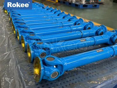
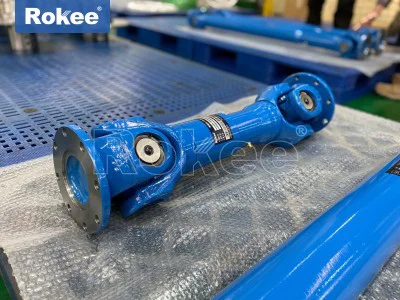
Universal Joint Coupling For Fan

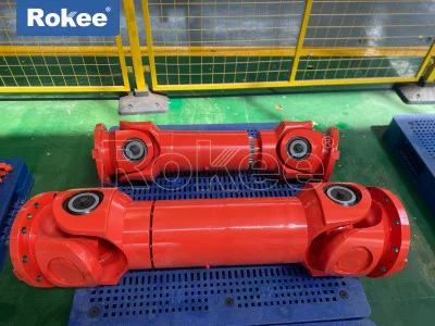
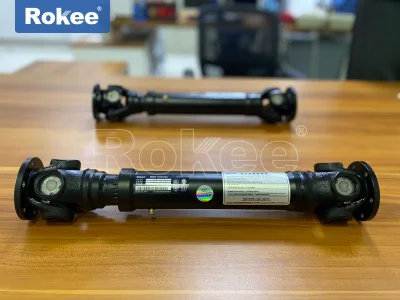
A universal joint coupling for fan is a mechanical transmission component that connects the fan shaft to the driving shaft while allowing angular, radial, or axial displacement between the two. In industrial ventilation, induced draft systems, forced draft units, large process fans, and ventilation blowers, the motor and fan are rarely mounted on perfectly collinear axes. Thermal expansion of the shafting, settling of the foundation, deflection of the base frame, vibration during startup, and deliberate spatial separation between driver and driven equipment all create a need for a flexible interface. The universal joint coupling absorbs these offsets without imposing harmful side loads on the bearing systems of either machine. Its core function is to transmit rotation and torque reliably from the prime mover—typically an electric motor, steam turbine, or internal combustion engine—to the fan impeller, while accommodating the geometric errors that inevitably appear in a real installation. Unlike a rigid sleeve, which would force perfect alignment and rapidly destroy bearings, the universal joint coupling tolerates misalignment and keeps the fan rotating smoothly. This role becomes especially important in heavy-duty fans, where the inertia of the impeller is large and any imbalance transmitted back to the motor can cause premature failure of windings, bearings, or gearboxes. The coupling is therefore not an afterthought in fan system design; it is the critical link that protects both the driver and the driven equipment from each other's imperfections.
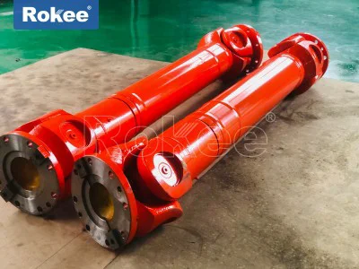
At its heart, the universal coupling relies on a universal joint, also known as a Cardan joint or Hooke's joint, to transmit rotary motion between intersecting shafts. A single universal joint consists of two yokes, one attached to each shaft, and a cross-shaped central element called a trunnion or spider, whose four bearing journals fit into needle bearings pressed into the yokes. When the two shafts are at an angle, the spider pivots on its bearings, allowing the driven shaft to continue rotating even though its axis is offset from the driving axis. A well-known characteristic of a single Cardan joint is that the output speed fluctuates twice per revolution when the shafts are angled, because the trigonometric relationship between the input and output angles is nonlinear. To eliminate this speed fluctuation in fan drives, engineers almost always use a double universal joint arrangement, in which two universal joints are connected by an intermediate shaft and the offset angles at each end are arranged to cancel out. This configuration, often called a universal joint shaft or driveshaft, delivers nearly constant velocity rotation across the working misalignment range. The needle bearings at each trunnion are lubricated and sealed, allowing the joint to rotate under high torque at moderate to high speeds. The geometry of the spider, the clearance in the bearing caps, and the stiffness of the yokes all determine how smoothly torque is transferred and how well the coupling survives under continuous fan duty.
Fans impose a distinctive set of demands on a coupling because they combine large rotational inertia, intermittent airflow loads, and often a wide speed range. When a fan starts, the impeller must accelerate from rest to operating speed while overcoming both bearing friction and the aerodynamic drag of the air it begins to move. This startup torque spike can be two to three times the running torque, and the coupling must carry that spike without permanent deformation. Once running, a fan experiences a steady but pulsating torque load: each blade passes through the wake of the stationary inlet guide vanes or the outlet volute tongue, creating a small periodic torque ripple. The universal joint coupling smooths this ripple by allowing a tiny amount of relative angular displacement between the shafts, so the motor does not feel every blade passage as a shock. At the same time, fans are notorious for producing vibration, whether from impeller imbalance, dirty blades, bearing looseness, or resonance with the surrounding ductwork. A rigid coupling would transfer that vibration directly into the motor, while a properly selected universal joint coupling attenuates it through the compliance built into the joint bearings and the freedom of the intermediate shaft to flex slightly. This isolation extends the life of motor bearings and reduces the likelihood of shaft fatigue cracking, which is a common failure mode in long, overhung fan shafts.
The construction materials used in a universal joint coupling for fans are chosen to balance strength, fatigue resistance, wear resistance, and corrosion protection. The yokes and intermediate shaft are typically forged from alloy steel, heat-treated to a hardness that resists both bending fatigue at the bolted ends and torsional fatigue along the shaft body. The spider, being the highest-wear element, is machined from through-hardened or carburized steel, and its four bearing journals are polished to a surface finish that minimizes fretting inside the needle bearings. Needle bearings are preferred over plain bronze bushings in most fan universal joints because they offer lower friction, higher load capacity in a compact envelope, and predictable service life under oscillating motion. The bearing caps are retained by either circlips or bolted plates, and the joints are sealed with rubber or synthetic rubber boots and gaskets to keep lubricant in and dust out. In aggressive environments—fans handling corrosive gases, humid marine air, or outdoor installations—the external surfaces may be zinc-phosphated, painted, or coated with a metallic barrier, while the fasteners at the flange ends are plated or made from stainless steel. The bolted flanges that connect the coupling to the motor and fan shafts are dimensioned so that the bolt group transfers the rated shear and clamping torque without slip; keyways or shrink fits may be used at the shaft hubs depending on the torque level. Material selection also accounts for temperature: fans in exhaust applications can see sustained inlet air temperatures well above ambient, and the coupling must retain its hardness and lubricity at those temperatures without overheating the bearing seals.
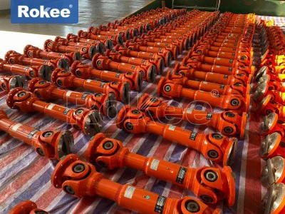
Several configurations of universal joint coupling are found in fan drive trains, and the choice depends on the misalignment envelope, the distance between shafts, the torque rating, and the speed. The single universal joint is rare in modern fan installations because of its speed fluctuation, but it still appears in low-speed, low-power auxiliary fans where cost and simplicity outweigh smoothness. The double universal joint with a straight intermediate shaft is the workhorse arrangement: it accommodates parallel and angular offset simultaneously and is used when the motor and fan share a common baseplate but cannot be perfectly aligned. When the shaft separation is large, as in belt-drive or long-line shaft arrangements between a motor room and a fan mounted on the roof of a building, an extended universal joint shaft with bearing supports in the middle is used to keep the intermediate shaft within its critical speed. For very high-power fans running at high speed, universal joints with a sliding spline in the intermediate shaft are specified, so that axial thermal expansion of the shafting can be absorbed without forcing the bearings apart. Some fan applications combine a universal joint coupling with an elastomeric element at one end, producing a hybrid coupling that adds torsional damping to the angular freedom of the Cardan joint. The length of the intermediate shaft, the diameter of the tubing, and the wall thickness are all sized to stay below the first lateral critical speed at the maximum operating rpm, because a shaft that passes through resonance will destroy itself and its bearings within minutes.
Installing a universal joint coupling on a fan system is a procedure that rewards care and patience, because even a well-engineered coupling will underperform if it is fitted incorrectly. The first step is to verify that the fan shaft and motor shaft are clean, undamaged, and within tolerance on their bearing journals, and that the keyways have no burrs or sharp edges that would stress the coupling hubs. The hubs are then fitted to the shafts using the manufacturer's recommended interference or shrink fit, and the bolts at the flanges are torqued in a diagonal sequence to the specified value, with the flange faces checked for full contact. With the coupling halves in place, the technician sets the initial angular and offset alignment between motor and fan, aiming for the intersection of the two shaft centers to fall within the coupling's rated misalignment envelope, not at zero. Over-aligning a fan drive to absolute perfection is actually counterproductive, because the universal joint coupling needs a small working angle to keep its needle bearings rolling; if the joint sits at zero angle for long periods, the bearing rollers create polished depressions in the races and eventually spall. The intermediate shaft must also be installed with the correct phasing: the two yokes at either end need to be in the same plane for a double Cardan joint to deliver constant velocity rotation. After mechanical installation, the joints are greased through the supplied fittings until clean grease appears at the seals, and the system is jogged to confirm that the coupling rotates freely without rubbing on any guard or duct. The coupling guard, which is a safety-critical element, is then fitted with adequate clearance so that no contact occurs at maximum misalignment and maximum shaft travel.
Maintenance of a universal joint coupling for fan centers on lubrication, alignment verification, and wear inspection. Because the joints operate continuously under load, the grease inside the needle bearings slowly oxidizes and is squeezed out at the seal lips, so a scheduled relubrication interval—often every few months to a year, depending on speed and environment—is essential. Over-greasing is just as harmful as under-greasing, because excess pressure can blow out the seals and allow contaminants in; the practice is to inject grease slowly while rotating the shaft, stopping when the seal just begins to bulge. Alignment should be rechecked after the first few weeks of operation, because the base, the grout, and the bearing seats settle and shift slightly as the machine goes through its first thermal cycles. Periodic vibration measurements at the fan and motor bearings provide an early warning: a growing once-per-revolution vibration at the coupling often indicates a worn spider or a loose bolt, while a twice-per-revolution component points to a speed fluctuation from an incorrectly phased universal joint. The spiders, boots, and bearing caps should be visually inspected at each maintenance stop, looking for rust at the seal lips, brinelling marks on the trunnions, or fretting cracks at the root of the yokes. When a universal joint shows measurable play—detectable by gripping the intermediate shaft and trying to rock it axially or radially—it is time to replace the spider kit rather than wait for a sudden failure. Keeping spare spider and bearing kits on site is standard practice for continuous-process fans, where an unplanned shutdown of the induced draft fan can force the entire plant to stop.
Vibration behavior is one of the most important reasons to choose and set up a universal joint coupling correctly in a fan system. Fans generate several distinct vibration sources: aerodynamic excitation from the blade pass frequency, mechanical imbalance of the impeller, flow-induced pulsation in the volute, and torsional ripple from the motor drive. The coupling acts as a filter between these sources and the motor bearings, and its dynamic characteristics determine how much of each vibration reaches the structure. A universal joint coupling is relatively stiff in torsion but flexible in bending, which means it transmits torque faithfully while allowing angular misalignment; this makes it good at attenuating lateral vibration caused by fan imbalance. However, it is not a torsional damper on its own, so if the fan drive train has a natural torsional frequency that coincides with the motor's startup ramp or with an aerodynamic pulsation frequency, a purely metallic universal joint can amplify that resonance rather than absorb it. In such cases, engineers add an elastomeric insert between the two yokes or choose a universal joint coupling with a resilient element, sacrificing a small amount of torque stiffness to gain damping. The rotating mass of the intermediate shaft also matters: at high speeds, an unbalanced driveshaft introduces its own once-per-revolution excitation, so balancing the assembled coupling to a reasonable quality grade is necessary, especially for long extended shafts. Installers must also watch for critical speed: if the intermediate shaft length approaches the length at which its first bending natural frequency equals operating speed, the shaft will whip, and the coupling, bearings, and fan seal will fail rapidly. Keeping the shaft diameter large enough and the support spacing short enough avoids this, and designers often calculate the critical speed explicitly during the layout phase.
Failure of a universal joint coupling in a fan installation follows a recognizable pattern, and understanding the failure modes helps both designers and maintenance crews prevent recurrence. The most common failure is wear of the spider bearings: as the needles brinell the raceways, play develops, the joint begins to thump once per revolution, and eventually a bearing cap disengages and the shaft drops. This is usually caused by running dry, by water ingress through a torn boot, or by operating the joint at too small an angle for too long, which causes the rollers to dwell in one spot and indent the races. A second common failure is fatigue cracking at the root of the yokes or at the flange transition, caused by repeatedly exceeding the rated torque during startup, by fitting the coupling with a shock load from a stalled fan, or by corrosion that reduces the effective cross-section. Shaft-to-hub slip, where the coupling hub rotates on the fan shaft despite the keyway, occurs when the interference fit relaxes from thermal cycling or when the bolted flange was never properly torqued, and it is often identified by fretting marks and rust streaks at the shaft interface. Seal failure is the slow-burning problem: once a boot cracks in dusty exhaust air, abrasive dust works into the needle bearings and grinds them to a seizure. When a coupling does fail in service, the response is not simply to bolt on a replacement and restart; the failed parts should be examined to identify whether the root cause was undersizing, misalignment, lubrication neglect, or a resonance issue, because the same root cause will destroy the next coupling within weeks. Keeping a failure file with photographs of broken spiders, worn trunnions, and cracked yokes is one of the most valuable maintenance practices a fan operator can develop.
Selecting the right universal joint coupling for a fan system requires matching the coupling's torque capacity, speed rating, misalignment envelope, and physical envelope to the actual duty, not just to the nameplate power. The first step is to establish the design torque: the rated torque of the motor multiplied by a service factor that accounts for startup frequency, aerodynamic load fluctuations, and the type of driven fan. Induced draft fans handling dirty gas often need a higher service factor than clean ventilation fans, and fans that start and stop several times a day need more margin than those that run continuously. The coupling must also be checked against the maximum shaft separation and the maximum angular offset expected during operation, including the offset that appears when the fan heats up and its housing expands relative to the motor. Speed rating is equally important: universal joints have a limiting speed beyond which the centrifugal force on the bearings and the whip of the intermediate shaft become unacceptable, and extending the shaft length to reach the fan may require a larger diameter tube or an intermediate support. Looking forward, the design of universal joint couplings for fans is evolving in two directions. On one side, condition-montegration is becoming standard: embedded sensors that measure coupling vibration, temperature, and play are being built into larger drives, allowing predictive maintenance that replaces scheduled greasing with data-driven intervention. On the other side, lightweight materials, improved bearing steels, and better sealing compounds are pushing the power density of these couplings higher, so that a fan drive can transmit more torque through a smaller, lighter universal joint that is easier to install and less sensitive to critical speed. Whether a plant operator is specifying a new induced draft fan for a power boiler, a ventilation blower for an underground garage, or a process fan for a chemical dryer, the universal joint coupling remains the quiet, dependable component that keeps the drive train aligned, protected, and running year after year.