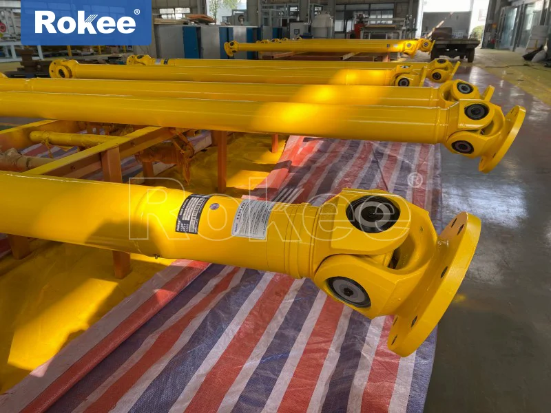
Mechanical Universal Shafts
A mechanical universal shaft, also commonly referred to as a cardan shaft, is a critical mechanical transmission component designed to connect two shafts that are not collinear or have angular misalignment, enabling the continuous transmission of torque and rotational motion between them. In modern industrial systems, from heavy-duty machinery to precision equipment, the mechanical universal shaft plays an irreplaceable role by addressing the challenge of power transmission in complex spatial layouts. Its design integrates sophisticated structural principles, superior performance characteristics, and diverse type classifications, all of which are closely tailored to the specific requirements of different application scenarios. To fully understand the value and functionality of this essential component, it is necessary to explore its structure, performance, types, and applications in detail, revealing how each aspect interacts to ensure reliable and efficient power transfer.
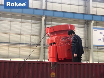
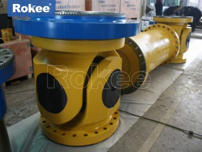
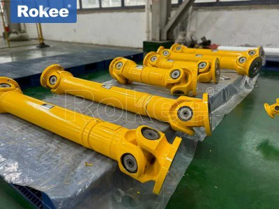
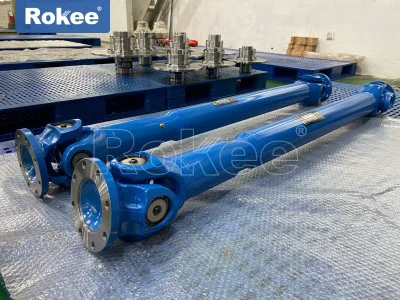
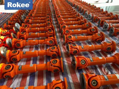
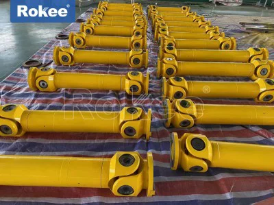
The structure of a mechanical universal shaft is inherently designed to accommodate angular, radial, and axial displacements between connected shafts, while maintaining stable torque transmission. At the core of its structure are several key components that work in harmony to achieve this functionality. The most fundamental components include yokes (also known as fork-shaped joints), a cross shaft (or spider), bearing assemblies, and connection mechanisms such as flanges or splines. The yokes are typically two U-shaped or Y-shaped components, each connected to the driving shaft and the driven shaft respectively. These yokes are designed with holes at their ends to accommodate the cross shaft, which serves as the intermediate connecting element. The cross shaft, as the central core, features four trunnions (extensions) that fit into the holes of the yokes, allowing the yokes to rotate relative to each other around the cross shaft’s center. To reduce friction and ensure smooth rotation between the cross shaft trunnions and the yoke holes, bearing assemblies are installed at each trunnion. These bearings are usually needle roller bearings or sliding bearings, selected based on the load and speed requirements of the application. Needle roller bearings are preferred for high-load, high-speed scenarios due to their compact size and ability to withstand significant radial loads, while sliding bearings are suitable for low-speed, heavy-load environments where dust and debris may be present. Additionally, sealing devices such as oil seals and dust caps are often integrated into the structure to protect the internal bearing components from contamination, preventing premature wear and extending the service life of the universal shaft. Some universal shafts also incorporate spline connections between the yoke and the shaft, which allow for axial movement to compensate for changes in the distance between the driving and driven shafts, further enhancing the component’s adaptability to dynamic working conditions.
The performance of a mechanical universal shaft is determined by its ability to transmit torque efficiently, accommodate misalignment, maintain stability under varying operating conditions, and resist wear and fatigue. One of the most prominent performance characteristics is its angular compensation capability, which allows the connected shafts to operate at an angle relative to each other without compromising torque transmission. Typically, standard universal shafts can accommodate angular misalignments ranging from 5° to 45°, with some specialized types capable of handling even larger angles. This flexibility is crucial in applications where the relative position of the shafts may change due to factors such as thermal expansion, structural deformation, or dynamic movement of the equipment. Another key performance attribute is transmission efficiency, which refers to the ratio of the torque delivered to the driven shaft to the torque input from the driving shaft. High-quality mechanical universal shafts achieve transmission efficiencies of 98% to 99.8%, minimizing energy loss and ensuring optimal utilization of power. This high efficiency is achieved through precise manufacturing of components, minimal friction in the bearing assemblies, and optimized structural design. Torque transmission capacity is also a critical performance factor, as universal shafts must be able to handle the specific torque requirements of their application. The torque capacity is determined by factors such as the material of the components, the size of the cross shaft and yokes, and the type of bearings used. Heavy-duty universal shafts can transmit extremely high torques, making them suitable for large industrial machinery, while lighter-duty models are designed for applications with lower torque demands. Additionally, mechanical universal shafts exhibit excellent dynamic stability, particularly when properly balanced. Dynamic balancing ensures that the shaft rotates smoothly at high speeds without generating excessive vibration, which can cause damage to other components in the transmission system. Some universal shafts are also equipped with damping elements or elastic components to absorb shock and reduce vibration, further improving the stability of the entire system. Wear resistance and durability are also essential performance characteristics, as universal shafts often operate in harsh environments with high loads, high speeds, or exposure to dust, moisture, and corrosive substances. The use of high-strength materials such as alloy steel, combined with surface treatments like carburizing and quenching, enhances the hardness and wear resistance of critical components, ensuring a long service life even under demanding conditions.
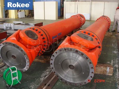
Mechanical universal shafts are available in a variety of types, each designed to meet specific application requirements based on factors such as torque capacity, angular misalignment, speed, and installation space. The classification of universal shafts can be based on several criteria, including structure type, torque capacity, and compensation performance. One of the most common classification methods is based on structural design, which yields three main types: cross shaft type, ball cage type, and ball fork type. The cross shaft type universal shaft is the most widely used due to its simple structure, high torque capacity, and excellent angular compensation capability. It consists of the basic components mentioned earlier—yokes, cross shaft, and bearings—and is available in both single and double cross shaft configurations. A single cross shaft universal shaft is suitable for applications with small to moderate angular misalignments and low to medium speeds, but it may produce periodic speed fluctuations when the angular misalignment is large. To address this issue, double cross shaft universal shafts are often used, which consist of two single cross shaft joints connected by an intermediate shaft. This configuration eliminates speed fluctuations by ensuring that the angular misalignments of the two joints cancel each other out, enabling uniform speed transmission even at large angles. The ball cage type universal shaft, also known as a constant velocity (CV) joint, is designed for high-speed, high-precision applications where uniform speed transmission is critical. It features an outer sleeve, an inner star-shaped ring, a cage, and several steel balls that are evenly spaced in the cage. The steel balls roll along specially designed grooves in the outer sleeve and inner ring, ensuring that the driving and driven shafts rotate at the same speed regardless of the angular misalignment. This type of universal shaft is compact in size, has low vibration and noise, and is commonly used in precision machinery, industrial robots, and automotive drive systems. The ball fork type universal shaft is another structural variant, which uses a ball fork and transmission balls to achieve torque transmission. It is simpler in structure than the ball cage type and is suitable for applications with moderate angular misalignments and lower speed requirements. In addition to these main structural types, universal shafts can also be classified based on torque capacity into heavy-duty, medium-duty, light-duty, and small-duty models. Heavy-duty universal shafts are designed for large industrial equipment such as rolling mills, mining crushers, and ship propulsion systems, capable of transmitting extremely high torques. Medium-duty models are used in applications such as agricultural machinery and conveyor systems, while light-duty and small-duty universal shafts are suitable for small appliances, instrumentation, and light industrial equipment. Another classification is based on compensation performance, with some universal shafts designed to compensate only for angular misalignment, while others can accommodate axial and radial displacements as well. Telescopic universal shafts, for example, feature a spline connection that allows for axial movement, making them ideal for applications where the distance between the driving and driven shafts changes during operation.
The applications of mechanical universal shafts are extensive and span across numerous industries, reflecting their versatility and adaptability to different working conditions. In the metallurgical industry, universal shafts are essential components in rolling mills, where they connect the motor to the rolling stands. Due to the high temperatures and heavy loads in rolling mills, the universal shafts used here must have high torque capacity, excellent heat resistance, and the ability to accommodate angular misalignments caused by thermal expansion of the equipment. They ensure the continuous transmission of power to the rolling rolls, enabling the production of steel sheets, bars, and other metal products. In the automotive industry, universal shafts are used in the drivetrain systems of vehicles, particularly in rear-wheel-drive and four-wheel-drive vehicles. They connect the transmission to the drive axle, allowing for angular misalignment between these components as the vehicle moves over uneven terrain. Ball cage type universal shafts are commonly used in front-wheel-drive vehicles to transmit power to the front wheels while accommodating the steering angle. In the construction and engineering machinery industry, universal shafts are found in equipment such as excavators, cranes, and loaders. These machines often have complex spatial layouts, with components that move relative to each other, and universal shafts enable reliable power transmission between non-collinear shafts. For example, in excavators, universal shafts connect the hydraulic motor to the swing mechanism, allowing the upper structure to rotate relative to the lower chassis while maintaining power transmission. The mining industry also relies heavily on universal shafts, which are used in crushers, conveyors, and mining trucks. These applications require universal shafts to withstand extremely high loads, harsh environmental conditions (such as dust and moisture), and frequent angular and axial displacements. In the aerospace industry, precision universal shafts are used in aircraft engines and control systems, where high reliability, low weight, and precise speed transmission are critical. They connect various components of the engine and flight control system, ensuring smooth and efficient operation even under extreme conditions such as high temperatures and vibrations. The agricultural industry uses universal shafts in tractors, harvesters, and other agricultural machinery, where they transmit power from the tractor’s engine to various implements such as plows, harrows, and mowers. These universal shafts must be durable, easy to maintain, and capable of accommodating the dynamic movements of agricultural equipment. Additionally, universal shafts are used in a wide range of other applications, including industrial robots, precision machine tools, textile machinery, printing machinery, and marine equipment. In each of these applications, the universal shaft is tailored to the specific requirements of the equipment, ensuring reliable, efficient, and stable power transmission.
The design and selection of a mechanical universal shaft are critical to ensuring optimal performance and reliability in any application. Several factors must be considered during the selection process, including the required torque capacity, the maximum angular misalignment, the operating speed, the installation space, and the environmental conditions. The torque capacity of the universal shaft must be sufficient to handle the maximum torque generated by the driving shaft, with a safety margin to account for unexpected load spikes. The angular misalignment capacity must match the maximum angle between the connected shafts, ensuring that the universal shaft can accommodate all possible relative movements without causing excessive wear or vibration. The operating speed is also a key factor, as high-speed applications require universal shafts that are dynamically balanced and have low friction bearings to prevent vibration and premature failure. Installation space constraints may dictate the use of compact universal shaft types, such as ball cage type or small cross shaft type models. Environmental conditions, such as temperature, humidity, dust, and corrosive substances, influence the selection of materials and sealing devices. For example, universal shafts used in high-temperature environments may require heat-resistant materials and lubricants, while those used in corrosive environments may need corrosion-resistant coatings or materials such as stainless steel. Proper maintenance is also essential to ensure the long service life of a mechanical universal shaft. Regular lubrication of the bearing assemblies reduces friction and wear, while periodic inspection of components such as the cross shaft, yokes, and seals helps to identify potential issues before they lead to failure. Lubrication intervals depend on the operating conditions, with more frequent lubrication required for high-load, high-speed, or harsh environments.
In conclusion, the mechanical universal shaft is a versatile and essential component in modern mechanical transmission systems, with a structure designed to accommodate misalignments, performance characteristics that ensure efficient and reliable power transmission, a variety of types tailored to different applications, and a wide range of uses across numerous industries. Its ability to connect non-collinear shafts and transmit torque continuously makes it indispensable in scenarios where traditional rigid shafts cannot be used. As industrial technology continues to advance, the design and performance of mechanical universal shafts are also evolving, with improvements in materials, manufacturing processes, and structural design leading to higher torque capacities, better angular compensation, and longer service lives. Whether in heavy-duty industrial machinery, precision equipment, or everyday vehicles, the mechanical universal shaft plays a crucial role in ensuring the smooth and efficient operation of mechanical systems, making it a cornerstone of modern engineering and manufacturing.
-
![Cardan Driveshaft Empowers Intelligent Upgrade Of Rock Wool Sandwich Panel Machinery]()
Cardan Driveshaft Empowers Intelligent Upgrade Of Rock Wool Sandwich Panel Machinery
-
![Cardan Drive Shaft Helps PIR Sandwich Panel Making Machinery Run Accurately]()
Cardan Drive Shaft Helps PIR Sandwich Panel Making Machinery Run Accurately
-
![Universal Coupling Empowers Intelligent Transmission Upgrading Of Sandwich Panel Lines]()
Universal Coupling Empowers Intelligent Transmission Upgrading Of Sandwich Panel Lines
-
![Selection Misunderstandings And Avoidance Methods Of Cardan Shaft Coupling In Continuous Sandwich Panel Production Line]()
Selection Misunderstandings And Avoidance Methods Of Cardan Shaft Coupling In Continuous Sandwich Panel Production Line
-
![Cardan Coupling Is The Key for Improvement Of Transmission Efficiency Of PU Sandwich Panel Production Line]()
Cardan Coupling Is The Key for Improvement Of Transmission Efficiency Of PU Sandwich Panel Production Line
-
![Cardan Shaft Empowers PU Sandwich Panel Machine For More Precise Transmission]()
Cardan Shaft Empowers PU Sandwich Panel Machine For More Precise Transmission
-
![Troubleshooting And Emergency Treatment Of Universal Coupling In PU Sandwich Panel Line]()
Troubleshooting And Emergency Treatment Of Universal Coupling In PU Sandwich Panel Line
-
![Perfect Adaptation Scheme Of Universal Shaft Coupling And Sandwich Panel Line]()
Perfect Adaptation Scheme Of Universal Shaft Coupling And Sandwich Panel Line