Large Size Universal Joint Coupling

Large size universal joint coupling represents a specialized heavy-duty transmission component engineered to deliver continuous torque transfer between shafts that cannot maintain perfect coaxial alignment, setting it apart from smaller universal joint units used in light machinery. Unlike compact universal joints designed for low to medium torque output, large size universal joint coupling is built to withstand extreme mechanical loads, large angular offsets, and sustained operation under heavy working conditions. Its core concept relies on articulated kinematics, allowing rotational power to pass between two shafts even when the centerlines form an angle during operation. In many heavy transmission layouts, two universal joint assemblies are arranged in pairs to counteract the inherent instantaneous speed variation that occurs with a single joint, which helps stabilize rotation and reduce vibration transmitted to connected equipment. The need for this type of coupling arises frequently in mechanical systems where mounting space, structural deformation, or thermal expansion makes rigid shaft connections impractical. Rigid couplings fail quickly when exposed to angular misalignment, as bending stress accumulates rapidly on shaft ends and fasteners. Large size universal joint coupling absorbs such misalignment through articulation rather than forcing shafts back into alignment, protecting prime movers, gearboxes, and working machines from damaging bending forces. Even when the relative angle between shafts changes gradually during operation, the coupling maintains power transmission without immediate failure, making it a preferred choice for dynamic heavy-load systems. Designers often evaluate the maximum operating angle, peak torque demand, and expected cycle duration before selecting this coupling type, as improper sizing can lead to premature wear of bearings and cross components. The basic mechanical logic remains consistent with smaller universal joints, but scaling up the structure introduces unique challenges related to material strength, heat generation, sealing, and dynamic balance that must be carefully handled in design and manufacturing.
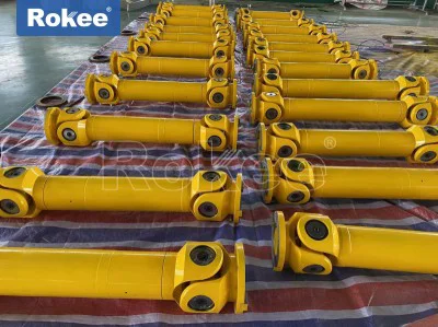
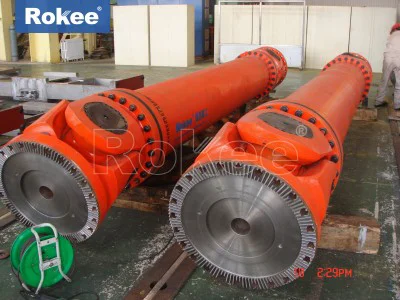
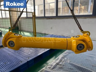
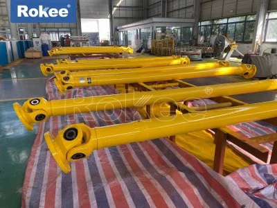
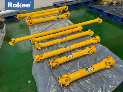
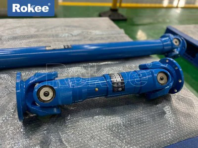
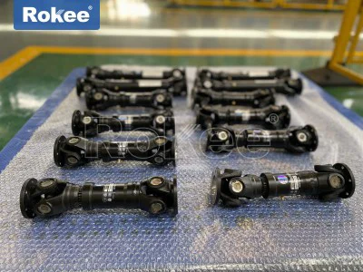
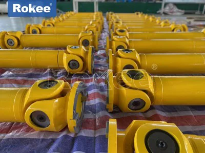
The physical construction of large size universal coupling is built around several primary load-bearing parts, each reinforced to handle heavy torque and repeated articulation. The fork-shaped yokes form the outer connecting ends, machined with precision bores to house bearing assemblies and secure the cross-shaped spider at the center. The cross spider acts as the central hinge element, with four perpendicular journals that fit into the bearing cups inside each yoke. Needle roller bearings are commonly fitted between the cross journals and yoke bores, minimizing sliding friction while supporting radial loads generated during rotation and angular deflection. Sealing assemblies surround the bearing cups to block dust, moisture, abrasive particles, and process contaminants from entering the bearing space, a critical feature for equipment operating in dirty industrial environments. Some versions include telescopic sections with mating splines, which compensate for axial displacement between connected shafts caused by thermal expansion, foundation settlement, or movement of machine frames. Every structural element is produced from high-strength alloy materials, subject to heat treatment processes that improve surface hardness and overall toughness, because surface fatigue and impact loading are the main failure modes for heavy-duty universal joints. Casting and forging methods are both used in production, with forged components typically selected for the highest load points due to improved internal grain structure and resistance to crack propagation. The geometry of yokes and cross spiders is optimized to avoid sharp stress concentration points, as stress peaks can develop quickly under fluctuating torque and cyclic bending. Tolerance control becomes more demanding as component dimensions increase; minor machining deviations can amplify vibration once the coupling rotates at operating speed, leading to accelerated bearing wear and loosening of retaining hardware. The integration of all these components creates a robust articulated mechanism that preserves power transmission while accommodating multiple forms of shaft misalignment simultaneously.
Understanding the operating mechanics of large size universal joint coupling helps clarify both its strengths and inherent limitations in heavy-duty transmission chains. When rotational torque enters the driving yoke, force transfers to the cross spider, which pivots within the bearing assemblies and drives the opposite yoke and connected driven shaft. The cross spider can pivot around two mutually perpendicular axes, which is what enables the coupling to function with angular misalignment between shaft centerlines. However, a single universal joint produces periodic fluctuation in instantaneous angular velocity as it rotates at a fixed offset angle. This speed variation creates cyclic torsional vibration that rises significantly as the working angle increases, potentially imposing fatigue loads on downstream machinery. To mitigate this effect, large size universal joint coupling systems are most often deployed in paired configurations, where two joints are positioned so the velocity variation of the first joint cancels out the variation of the second. This paired layout delivers near-constant velocity output to the driven shaft, as long as installation geometry follows the correct arrangement rules for yoke orientation and matching working angles. During rotation, the bearings at each cross journal experience combined rolling and sliding contact, generating friction heat that accumulates under continuous heavy load. Heat buildup accelerates lubricant degradation, which is why adequate lubrication management is essential for long service life. Even when operating within design limits, the articulating surfaces experience cyclic contact stress, and repeated load cycling can gradually create surface fatigue on bearing rollers and cross journal surfaces. When misalignment exceeds the design angle, mechanical stress rises sharply, vibration grows audible, and impact loads may damage the cross spider or fracture yoke sections. Proper understanding of these mechanical behaviors guides engineers to set safe operating boundaries and arrange the complete drive train to minimize unnecessary angular deflection.
Large size universal joint coupling finds extensive application in heavy industrial sectors where high torque transmission and adaptive misalignment compensation are essential. Metallurgical processing equipment depends heavily on this coupling type for rolling and straightening machinery, where large rotating rolls must receive power while structural movement and thermal expansion continuously shift shaft positions. Mining and bulk material handling systems also use large universal joint couplings to connect drive units for crushers and heavy conveyors, environments marked by heavy shock loads, airborne grit, and limited access for frequent maintenance. Construction machinery and heavy lifting equipment employ these couplings to transmit power through moving frame sections, where shaft alignment changes as booms and working arms shift position during operation. Marine deck machinery and offshore auxiliary drives adopt large size universal joint coupling to handle dynamic movement of equipment foundations and variable loading conditions on working decks. In material processing plants, rotating drums and mixing equipment rely on the coupling’s ability to sustain torque transfer even when machine frames deflect under heavy product weight. Each of these applications shares a common trait: rigid couplings would suffer rapid breakdown, while flexible couplings with elastomeric elements cannot withstand the magnitude of torque and shock loads present. In many installations, the coupling also serves as a mechanical safety buffer, absorbing sudden torque spikes that might otherwise damage gearboxes or prime movers. The selection process for these heavy-duty couplings starts with mapping torque cycles, maximum deflection angles, environmental conditions, and expected operating hours. Engineers also examine the space envelope available for installation, because large universal joint assemblies require sufficient room for articulation and maintenance access. Across all these fields, the coupling’s practical value lies in its combination of high torque capacity and controlled angular flexibility that few other transmission components can match.
Comparing large size universal joint coupling with other heavy-duty coupling options reveals its unique tradeoffs in performance, installation requirements, and service characteristics. Gear couplings can transmit very high torque and tolerate limited misalignment, but they rely on sliding contact between gear teeth and cannot accommodate large angular deflection. Elastomeric couplings provide good vibration damping, yet their torque capacity falls far below the levels handled by large universal joint couplings, and high heat or chemical exposure can degrade elastic materials quickly. Disc couplings maintain precise rotation under small misalignment values, but they become vulnerable to fatigue damage when angular offset increases beyond narrow limits. Large size universal joint coupling stands out because it accepts substantially larger working angles while transferring extreme torque, and it maintains stable operation under shock loading. Its main drawback is the inherent velocity fluctuation in single-joint setups, which requires careful layout planning when vibration control is critical. Another consideration is the need for regular lubrication, unlike some maintenance-free coupling designs that use sealed permanent lubrication for lighter loads. Dynamic balance also becomes more important with larger coupling mass; poorly balanced assemblies generate strong centrifugal forces at high rotational speeds, leading to noise and component fatigue. Installation is more involved as well, requiring technicians to align paired joints correctly and verify operating angles before commissioning. Foundation movement over time can alter shaft angles, so periodic inspection of alignment is recommended. Where operating speeds remain moderate and angular misalignment is unavoidable, large size universal joint coupling often emerges as the most practical solution. Where misalignment is minimal and vibration damping is the primary priority, alternative coupling styles may deliver better long-term performance. Recognizing these tradeoffs allows mechanical designers to select the right coupling type rather than defaulting to universal joint designs for every heavy transmission scenario.
Material selection and heat treatment are foundational to the reliability of large size universal joint coupling under heavy cyclic loads. All major load-bearing components, including yokes and cross spiders, are made from high-strength alloy formulations chosen for resistance to torsion, bending, and contact fatigue. Raw stock is processed using forging techniques for critical parts, which compress internal voids and orient the metal grain structure to follow force flow lines, improving resistance to crack initiation and propagation. Subsequent heat treatment modifies surface and core material properties; surface hardening creates a wear-resistant outer layer on cross journals and bearing contact zones, while the core retains ductility to absorb sudden impact loads. If surface hardness is excessive, components become brittle and prone to cracking under shock; if hardness is insufficient, wear accelerates quickly on bearing surfaces. Bearing elements are manufactured from specialized bearing-grade materials, processed to maintain dimensional stability under elevated operating temperatures. Sealing components are selected based on environmental exposure, with different compounds used for dry dusty settings versus environments with moisture, cooling liquids, or chemical sprays. Material selection also accounts for temperature variations, because extreme cold can reduce the flexibility of seal materials, while sustained high temperatures degrade lubricants and soften some alloy properties. Corrosion resistance is another consideration for outdoor or wet operating locations, where surface treatments may be applied to slow oxidation and chemical attack. Material defects such as internal inclusions or uneven grain structure can create failure points, which is why component inspection is performed after machining and heat treatment. Every material choice balances mechanical strength, wear resistance, thermal stability, and manufacturability. When the material specification does not match the working load profile, even a well-designed coupling geometry will suffer early failure from fatigue, abrasion, or fracture.
Lubrication and sealing systems play a decisive role in extending the service life of large size universal joint coupling, especially in harsh industrial working environments. Lubricant fills the space between needle rollers, bearing cups, and cross journal surfaces to reduce metal-to-metal friction during articulation and rotation. It also dissipates frictional heat generated by continuous rolling and sliding contact, prevents oxidation of contacting surfaces, and flushes away fine wear debris produced during operation. Different lubricant types are selected according to operating temperature range, load intensity, and environmental contamination levels. Heavy-duty grease formulations are widely used because they remain in bearing cavities better than liquid oil and maintain protection during intermittent operation. Lubrication points are built into the coupling structure, allowing fresh lubricant to be injected without complete disassembly in many designs. The sealing system works alongside lubrication, retaining lubricant inside bearing chambers while blocking abrasive particles, water, and process contaminants from entering the contact zones. Damaged seals are one of the most common causes of premature coupling failure; once grit enters the bearing assembly, abrasive wear accelerates rapidly on cross journals and roller surfaces. Seal integrity degrades over time from heat cycling, mechanical movement, and chemical exposure, so seal inspection forms a core part of routine maintenance. Over-lubrication can create excess internal pressure inside bearing housings, damaging seals and increasing rotational resistance, while under-lubrication leads to metal contact and overheating. Operators must follow appropriate refill intervals based on running hours and environmental severity. In highly contaminated locations, protective outer covers may be fitted to reduce direct exposure of the coupling assembly to airborne particles and debris. Properly maintained lubrication and sealing preserve the precision contact surfaces, reducing wear rates and preventing unexpected breakdown during continuous production cycles.
Installation and alignment practices directly influence the operating performance and service life of large size universal joint coupling, requiring careful attention during assembly and commissioning. Before installation, all components should be visually inspected for transport damage, including cracks, dents, or deformation on yokes and cross assemblies. Machined surfaces, bearing cavities, and spline interfaces must be cleaned thoroughly to remove residual machining debris or protective coatings that could contaminate bearings after startup. When installing paired universal joint arrangements, the angular orientation of the yokes must follow the required geometry to counteract speed variation and torsional vibration. Shaft alignment is adjusted to keep the operating angle within the designed range; excessive angle creates amplified vibration, heat generation, and fatigue loading. Axial positioning is also controlled carefully for couplings with telescopic spline sections, ensuring there remains enough sliding travel to accommodate thermal expansion and foundation movement without reaching the end of the spline range. Fasteners connecting the coupling yokes to equipment shafts are tightened in a controlled sequence to evenly distribute clamping force, avoiding distortion of hub bores. After assembly, manual rotation of the drive train helps technicians detect binding, abnormal friction, or interference between moving parts before power is applied. Initial startup should proceed gradually, with monitoring for unusual noise, vibration spikes, or rapid temperature rise at bearing locations. Even after successful commissioning, foundation settling or thermal deformation can slowly alter shaft angles over time. Regular rechecking of alignment reduces the risk of hidden overload developing inside the coupling. Poor installation often produces symptoms that are mistakenly attributed to defective components, such as early bearing failure or loosening of connecting hardware. Following structured installation procedures eliminates many avoidable failure modes and ensures the coupling functions as intended throughout its service cycle.
Monitoring and maintenance routines for large size universal joint coupling focus on detecting early signs of degradation before catastrophic failure interrupts production. Routine visual inspection checks for seal leakage, loose fasteners, cracks on yoke surfaces, or visible damage to protective covers. Auditory observation during operation can reveal abnormal knocking or rumbling sounds that indicate bearing wear, inadequate lubrication, or excessive operating angles. Vibration measurement is a valuable diagnostic tool; rising vibration levels often signal worn bearings, cross journal surface damage, or shifted shaft alignment. Temperature checks at bearing housings help identify overheating caused by insufficient lubrication, excess friction, or operating angles beyond design limits. Lubricant sampling, where possible, can reveal the presence of metallic particles, providing advance warning of surface wear inside bearing assemblies. Maintenance schedules are adjusted based on actual operating conditions. Couplings used in dusty, high-shock environments require more frequent inspection and lubrication than those running in clean, steady-load applications. During planned shutdowns, technicians can disassemble selected sections to examine bearing rollers, cross journal surfaces, and spline contact areas for pitting, scoring, or fatigue cracks. Worn components are replaced before their condition worsens, because partial damage to one bearing or cross element quickly transfers extra stress to other parts of the coupling. Reassembly after component replacement demands careful cleaning, fresh lubrication, and verification of alignment and yoke orientation. Maintenance records help track operating hours, lubrication events, and component replacement history, enabling trend analysis to predict remaining service life. Effective maintenance does not simply respond to breakdowns; it creates a proactive cycle that preserves transmission reliability and reduces unplanned downtime for heavy machinery systems.
As industrial mechanical systems continue to evolve, large size universal joint coupling remains a vital transmission component, with ongoing refinements focused on durability, efficiency, and operational safety. Modern development efforts target improved bearing geometry and surface finishing to reduce friction losses and lower heat generation under sustained heavy torque. Advances in sealing technologies deliver longer service intervals in heavily contaminated environments, decreasing the frequency of maintenance stops. Finite element analysis tools are widely used to simulate stress distribution across yokes, cross spiders, and bearing assemblies, helping designers refine shapes to reduce stress concentrations without sacrificing load capacity. Dynamic simulation also predicts vibration behavior across different operating angles and torque cycles, supporting optimized paired joint layouts for complex drive trains. Some updated designs integrate improved lubrication routing that ensures more consistent lubricant delivery to every bearing journal, even under extreme articulation. While these technical improvements enhance performance, the fundamental working principle of large size universal joint coupling remains unchanged, relying on articulated cross and yoke structures to transfer torque across misaligned shafts. Engineers continue to balance the benefits of high angular tolerance with the inherent mechanical limits of universal joint kinematics. Newer machinery designs often incorporate remote condition monitoring sensors that track vibration and temperature, allowing early fault detection without requiring physical access to the coupling assembly. Despite the emergence of alternative transmission concepts, large size universal joint coupling retains its position in heavy industry because few competing solutions can match its combination of high torque handling and large angular deflection capability. The continued use of this coupling demonstrates that proven mechanical concepts can stay relevant when refined with modern material science, simulation methods, and condition monitoring practices, supporting reliable heavy power transmission for many generations of industrial equipment.