Composition Of Universal Joint Coupling
Universal joint coupling is a mechanical device used to connect different axes and transmit torque. Its core function is to compensate for the angular deviation and relative displacement between the two axes. According to different structures and working principles, universal joint couplings can be divided into various types. The following is a detailed explanation of their typical composition structure and classification:
Core components
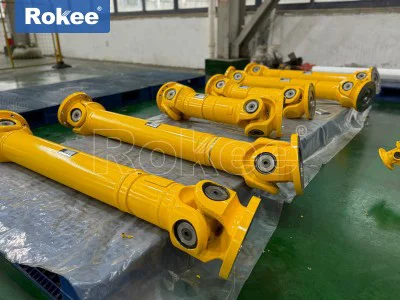
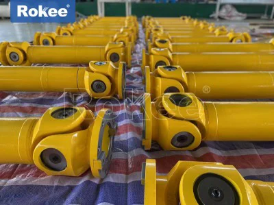
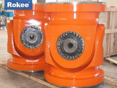
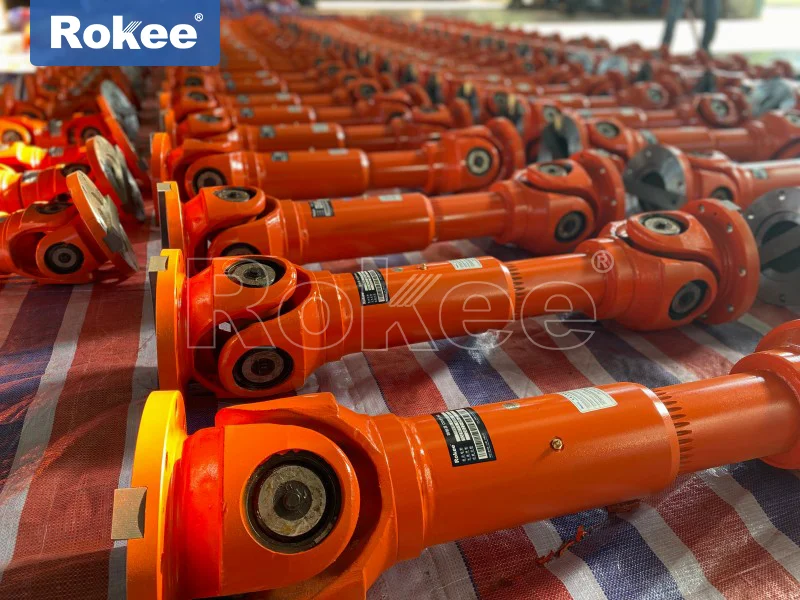
Cross shaft universal joint coupling
Cross shaft: the core transmission component, connected to the universal joint fork at all four ends through bearings, allowing axial swing. Universal joint fork: It is connected to the driving shaft and the driven shaft respectively, forming a power transmission channel. Needle roller bearing: installed on the cross shaft neck to reduce friction and withstand radial loads. Sealing and lubrication system: including oil seals, oil injectors, etc., to ensure long-term stable operation of bearings.Ball cage universal joint coupling: The spherical outer ring and star shaped inner ring transmit torque through the cooperation of the inner and outer raceways. Transmission steel balls: 6-8 steel balls are evenly distributed in the cage to ensure constant speed transmission. Holder: Fix the position of the steel ball so that it is on the bisector of the angle between the two axes. Dust cover: protects the internal lubricating grease and prevents contaminants from entering.
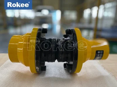
Ball joint/ball pin universal joint coupling
Ball head and socket: Multi angle swing is achieved through spherical contact surface. Elastic components: such as polymer buffer sleeves, used for vibration and noise reduction. Limit structure: Adjust the axial displacement range to avoid overload.
Auxiliary structural components
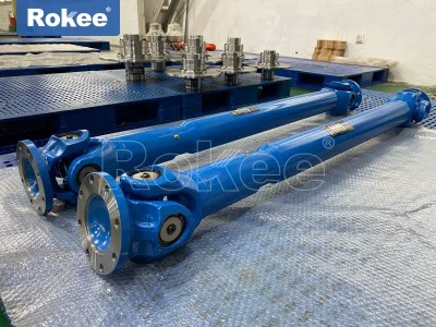
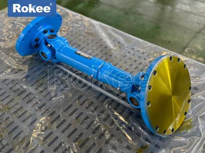
The transmission shaft is used to connect the universal joints at both ends, and some are designed to be extendable to adapt to changes in wheelbase. During high-speed operation, it is necessary to perform dynamic balancing to prevent vibration.
Intermediate support
is used for intermediate support of long transmission shafts, usually containing rubber damping elements to compensate for installation errors.Connectors such as flanges, splines, bolts, etc. are used to secure the coupling to the shaft end.
Main classifications and characteristics
Cross axis universal joint features: simple structure, strong load-bearing capacity, but needs to be used in pairs to achieve constant speed transmission. Application: Heavy machinery, metallurgical equipment, etc.
Ball cage universal joint (constant velocity universal joint)
Features: smooth transmission, allows for large deflection angles, suitable for high-speed scenarios. Applications: Automotive drive axles, precision machinery.Characteristics of ball joint plunger universal joint: It combines sliding and rolling transmission modes, with large axial compensation. Application: Construction machinery, ship propulsion systems.
Features of dual universal joint: By combining the intermediate shaft with universal joints at both ends, it achieves complete constant speed transmission. Application: Industrial equipment that requires high synchronization accuracy.
Materials and processes
Material: Commonly used 45 # steel and 40Cr alloy steel, which have been carburized, quenched or tempered to improve wear resistance.
Lubrication: Most use lithium based grease, while some high-speed models require circulating oil lubrication.
Sealing: Multi layer rubber dust cover or metal sealing ring to prevent grease leakage.
Key parameters for selection
Torque capacity: Select nominal torque according to load requirements.
Allowable deviation angle: Single section usually 5 ° -45 °, double section can reach 75 °.
Speed limit: High speed scenarios require the selection of models with higher dynamic balance levels.
Environmental adaptability: Corrosive environments require stainless steel or special coatings.
Through reasonable selection and maintenance, universal joint couplings can effectively solve complex shaft transmission problems and are widely used in fields such as automobiles, metallurgy, and petroleum machinery.