Cardan Shaft for CNC Machines

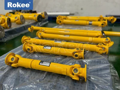
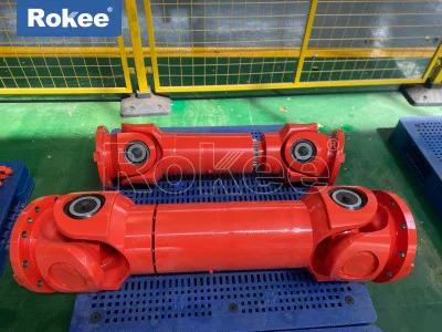
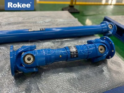
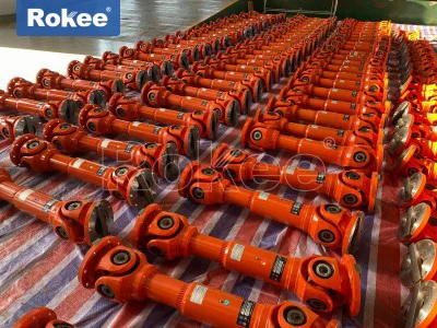
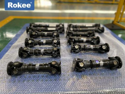
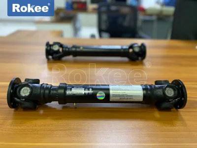
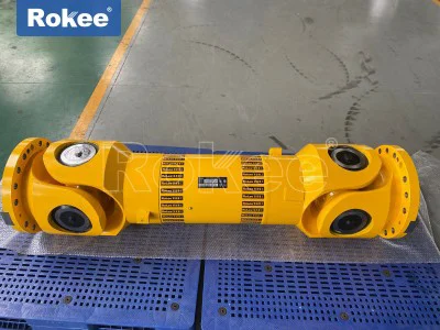
A cardan shaft, also widely recognized as a universal joint shaft, serves as a vital transmission component within modern CNC machine systems, designed to transfer torque and rotational motion between driving and driven shafts that cannot maintain perfect coaxial alignment. Unlike rigid shaft connections that require precise linear alignment and fail to accommodate any angular or axial deviation, the cardan shaft introduces articulated flexibility into the power chain of CNC equipment. In many CNC configurations, the layout of motors, gearboxes, spindles and rotary worktables creates spatial constraints that make straight shaft mounting impractical. Machine frames may experience minor deflection under heavy cutting loads, and thermal expansion during prolonged operation can shift the relative positions of connected drive units. These subtle displacements would impose enormous stress on fixed couplings, leading to binding, bearing damage and degraded machining consistency. The cardan shaft addresses these physical challenges by allowing controlled angular deflection, radial offset and axial sliding movement while continuously transmitting rotary force. Its core assembly centers on cross-shaped universal joints fitted with precision needle roller bearings, which enable smooth pivoting between two yoke structures. This simple yet sophisticated mechanical concept has been adapted to meet the strict precision demands of CNC environments, where even small irregularities in power delivery can directly affect surface finish, dimensional accuracy and overall part quality. As CNC machines evolve toward higher spindle speeds and heavier cutting capacities, the role of the cardan shaft becomes increasingly important, bridging the gap between power sources and working mechanisms without sacrificing mechanical stability during dynamic machining cycles.
The basic working principle of a cardan shaft for CNC machines relies on the coordinated motion of its universal joint modules, and understanding this mechanism helps machine operators anticipate performance limits during operation. A single cardan joint consists of two fork-shaped yokes connected by a cross spider with four trunnions, each supported by needle roller bearings. When the driving yoke rotates, it pushes the cross spider, which then transfers rotary movement to the driven yoke. A single universal joint generates periodic speed fluctuation if the connected shafts operate at an angle, which is unacceptable for CNC applications requiring steady rotational velocity. For this reason, most cardan shafts fitted to CNC equipment adopt a double-joint layout, with two universal joints mounted on an intermediate tubular shaft. When arranged properly, the velocity variation produced by the first joint cancels out the fluctuation from the second joint, delivering nearly uniform rotation to the downstream component. Many designs also integrate splined sliding sections between the intermediate tube and joint yokes, allowing the total length of the shaft to adjust automatically as thermal expansion or mechanical movement changes the distance between connected machine units. This axial compensation eliminates compressive or tensile loads that would otherwise build up inside the transmission system. In CNC rotary axes and auxiliary spindle drives, this combination of angular flexibility and length adjustment ensures torque transfer remains stable whether the machine operates at low speed for heavy stock removal or higher speed for finishing passes. Even small misalignments that naturally emerge after machine reassembly or long-term use can be absorbed by the articulated structure, preventing shock loads from propagating through gears and spindle bearings.
Material selection for cardan shafts intended for CNC machines is governed by the competing demands of high torque resistance, low rotating mass, wear resistance and dimensional stability under temperature changes. The main intermediate tube is typically fabricated from alloy steel, chosen for its high tensile strength and ability to resist twisting deformation under continuous torque loads. The cross spider and yokes are made from hardened alloy steel, which undergoes heat treatment processes to achieve a tough core and hard outer surface; this combination prevents surface wear on bearing contact points while resisting brittle fracture under intermittent cutting shocks. Needle roller bearings are carefully sized to distribute contact pressure evenly across the trunnion surfaces, reducing local stress concentration during rotation. Surface finishing treatments are applied to critical moving surfaces to reduce friction and guard against corrosion, especially in CNC workshops where coolant mist and fine metal particles fill the operating environment. Material density is also an important consideration, as excessive mass in rotating components increases centrifugal force and raises vibration risk at high speeds. Engineers balance wall thickness and material grade to keep the shaft lightweight without sacrificing torsional rigidity. If the material lacks sufficient hardness, the bearing contact surfaces will wear quickly, creating backlash and rotational play that distorts positioning accuracy in CNC rotary axes. Conversely, overly brittle materials risk cracking under sudden load spikes during interrupted cutting. The material stack for CNC cardan shafts must therefore be selected to withstand cyclic loading, temperature variation and exposure to workshop contaminants, preserving consistent transmission performance over thousands of operating hours.
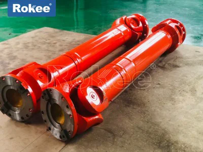
Structural design variations of cardan shafts allow adaptation to different CNC machine types, ranging from compact vertical machining centers to large gantry systems and multi-axis rotary equipment. Short, rigid cardan shaft assemblies are commonly used for small rotary tables and auxiliary drive units, where space is limited and angular misalignment remains modest. Longer versions with reinforced intermediate tubes are deployed on large-format CNC machines, where the drive motor sits far from the working spindle or rotary mechanism, and greater axial movement must be accommodated. The splined sliding section, a key modular feature, can be internal or external depending on installation geometry, and it maintains precise fit while extending or retracting. Flange connections at both ends of the shaft assembly are engineered with accurately positioned bolt holes to ensure concentric mounting to motor flanges, gearboxes or spindle input flanges. Some designs use welded connections between the intermediate tube and yoke bases, while others employ bolted structures that simplify disassembly for inspection and part replacement. The arrangement of the two universal joints represents the most critical design choice for CNC precision applications; the yokes must be aligned in a specific phase so that angular velocity fluctuations cancel each other. Incorrect phase alignment will introduce cyclic speed ripple, which translates into visible chatter marks on machined workpieces and accelerated wear on all linked drive components. Every structural detail is refined to match the machine’s torque range, operating speed and expected misalignment envelope, ensuring the cardan shaft integrates seamlessly into the machine’s kinematic chain without introducing new sources of positional error.
Installation and alignment procedures heavily influence the service performance of cardan shafts on CNC machines, and improper setup can negate many of the component’s inherent advantages. Before installation, technicians inspect mating flange surfaces to remove burrs, coolant residue and metal debris that could create uneven contact and tilt the shaft assembly. The shaft is positioned so that the operating angle of each universal joint stays within the designed working range. While cardan joints can tolerate angular offset, excessive angles amplify bearing loads and speed variation, shortening service life and introducing vibration into the machine drive system. The two yokes of the double cardan assembly must be oriented correctly to achieve constant output rotation, and angular deflection at both ends should be kept as equal as possible. Axial clearance of the splined sliding section must also be checked, ensuring there is enough room for thermal expansion without creating end thrust. After mounting, manual rotation of the complete drive train reveals binding or rough spots that indicate misalignment or interference with nearby machine structures. Once the mechanical fit is confirmed, many operators perform low-speed dry runs to monitor noise and vibration before loading workpieces for cutting. Even after initial successful installation, machine maintenance events such as spindle overhaul or frame realignment can alter shaft geometry, requiring rechecking of angles and flange seating. Careful installation does not eliminate all misalignment, but it ensures the cardan shaft works within its intended operating window, protecting expensive CNC drive components and maintaining the high positional accuracy required for precision machining tasks.
Vibration and dynamic balance represent critical performance considerations for cardan shafts used in CNC equipment, because unbalanced rotating mass directly undermines machining quality. During high-speed rotation, any uneven mass distribution around the shaft axis generates centrifugal force that creates periodic vibration. This vibration travels through the machine structure, producing chatter on cutting edges and leaving wavy surface patterns on finished parts, while also accelerating fatigue in bearings and gear teeth. For this reason, finished cardan shafts for CNC applications undergo dynamic balance testing after assembly. During testing, the shaft rotates at controlled speeds while sensors measure vibration amplitude, allowing material to be removed from designated balance surfaces to correct mass asymmetry. The balance quality targets are set according to the maximum operating speed of the CNC machine; higher spindle speeds demand tighter balance tolerances. Even a well-balanced cardan shaft will still produce some vibration if operating at excessive joint angles, as the mechanical motion of universal joints creates inherent cyclic forces. Machine designers mitigate this by limiting working angles and adding structural damping within the machine frame. Operators should monitor vibration levels during routine CNC operation, as rising vibration often signals worn bearings, loosened flange bolts or degraded spline fit inside the cardan shaft. Detecting these changes early prevents gradual deterioration of machining accuracy and avoids unexpected machine downtime in the middle of production batches.
Wear patterns and failure modes of CNC cardan shafts follow predictable trends, and recognizing early warning signs helps maintenance teams plan component replacement before catastrophic breakdown. The most common wear occurs within the needle roller bearings and trunnion surfaces of the cross spider. Lubricant degradation allows metal-to-metal contact, which gradually abrades bearing surfaces and creates backlash in the universal joint. As backlash increases, rotary motion becomes less precise; when the CNC controller commands a small angular movement of a rotary table, lost motion in the cardan joint delays the response and reduces positioning repeatability. Spline surfaces on the sliding section also wear over time, especially if fine abrasive dust from metal cutting enters the sliding interface. This wear leads to play in the axial direction and can cause impact loads during direction reversals. Fatigue cracking represents a more serious failure mode, usually starting at stress concentration points on yokes or cross spiders, caused by repeated cyclic torque and shock loads during interrupted cutting. Overloading beyond the designed torque capacity can twist the intermediate tube or shear the cross spider entirely, shutting down the machine. Audible cues often appear before total failure: rhythmic clicking noise during rotation, knocking when the drive reverses direction, or increased humming at high operating speeds. Rising operating temperature at the joint housing is another warning sign, indicating high friction inside bearings. By tracking these indicators, maintenance personnel can schedule servicing during planned downtime, rather than facing unplanned production interruptions and potential secondary damage to connected CNC drive hardware.
Lubrication and preventive maintenance practices directly extend the usable service life of cardan shafts in CNC machines and preserve their transmission precision. Most universal joint bearings rely on grease lubrication, which forms a separating film between needle rollers and trunnion surfaces to reduce friction and wear. The lubricant also acts as a barrier against fine metal chips, coolant mist and workshop dust that can abrade polished bearing surfaces. Over time, heat from continuous rotation breaks down grease, and contaminants gradually penetrate the joint housing, reducing lubrication effectiveness. Maintenance routines include periodic grease replenishment through built-in grease fittings, with intervals adjusted based on operating speed, load intensity and workshop environmental conditions. Excess grease should be avoided, as overfilling the joint housing creates internal pressure and raises operating temperature. During lubrication service, technicians visually inspect joint seals, which prevent the escape of grease and block the entry of foreign particles. Cracked or hardened seals allow contamination to accelerate bearing wear significantly. The splined sliding section also needs lubrication to maintain smooth length adjustment and reduce wear on mating tooth surfaces. Maintenance procedures also include checking bolt tension on flange connections, verifying alignment angles and examining the shaft surface for cracks or deformation. When maintenance is performed consistently, the cardan shaft maintains low backlash and smooth rotation, supporting the CNC machine’s ability to hold tight dimensional tolerances across long production runs.
Cardan shafts offer distinct advantages for CNC machine drive systems, yet they also carry inherent limitations that designers must account for when integrating them into machine kinematics. The primary strength lies in combined angular, radial and axial compensation capability, a feature rigid couplings cannot match. This flexibility simplifies machine layout design and absorbs misalignment from assembly, thermal growth and frame deflection under cutting loads. Cardan shafts can transmit high torque within a compact envelope and tolerate momentary shock loads during heavy cutting, protecting motors and gearboxes from sudden force spikes. The modular construction allows individual components such as bearings or cross spiders to be replaced without replacing the entire shaft assembly in many cases. However, the universal joint mechanism has inherent mechanical tradeoffs. A single joint creates rotational speed variation under angular deflection, requiring double-joint construction to deliver steady rotation, which adds assembly length and complexity. Even a properly configured double cardan shaft generates small cyclic forces, which can contribute to vibration at high rotational speeds. The bearings inside universal joints have finite service life, demanding regular lubrication and inspection, unlike some non-contact coupling styles with minimal maintenance needs. Operating life declines rapidly when working angles exceed recommended limits, or when fine abrasive workshop contaminants bypass sealing structures. These characteristics mean cardan shafts are not ideal for every CNC drive configuration, but they remain the preferred solution for applications where shaft misalignment cannot be fully eliminated and high torque transmission is required.
Looking ahead, the evolution of CNC machine design continues to shape improvements in cardan shaft engineering, with ongoing refinements focused on higher precision, lower vibration and extended service intervals. Modern simulation tools are used to model torque distribution, thermal deformation and dynamic stress across the full operating cycle of CNC equipment, enabling engineers to optimize yoke geometry, tube profile and bearing arrangement before physical prototypes are produced. Advanced surface treatment methods enhance wear resistance and corrosion protection, helping components survive longer in harsh workshop environments filled with cutting fluids and metallic dust. Improvements in sealing technology reduce contamination ingress, extending lubricant service life and lowering maintenance frequency. Balancing processes are also refined to minimize residual unbalance, supporting the push toward higher spindle and rotary axis speeds in next-generation CNC systems. As multi-axis CNC machines become more common, cardan shaft designs are tailored to fit compact rotary axes and complex kinematic arrangements, maintaining torque transmission while preserving the precise positioning required for intricate part geometries. Even with these advances, the fundamental mechanical nature of the universal joint remains unchanged, so proper selection, installation and maintenance will continue to determine real-world performance. The cardan shaft stays a foundational transmission element for CNC machinery, delivering the flexible connection needed to reconcile mechanical layout constraints with the strict demands of precision automated manufacturing.